Transcription of Technical Information How to Choose Ferrite …
1 Box J,One Commercial Row, Wallkill, NY 12589-0288 Phone:(888) FAIR RITE / (845) 895-2055 FAX:(888) Ferrite / (845) 895-2629 E-Mail: 324-7748(888) 337-7483 Note: (914) Area Code has changed to (845).Fair-Rite Products Edition174 Technical InformationHow to Choose Ferrite Componentsfor EMI SuppressionFigure 1 FCC Radiation Limits for class A & B Limits*FrequencyClass A Class B450 kHz MHz 60 dBuV 50 MHz 30 MHz 70 dBuV 60 dBuV*Measured using a 50-ohm LISNR adiated Limits**30 MHz 88 MHz 50 dBuV/m 40 dBuV/m88 MHz 216 MHz 53 dBuV/m 43 dBuV/m216 MHz 960 MHz 56 dBuV/m 46 dBuV/mabove 960 MHz 64 dBuV/m 54 dBuV/m**Measured at a 3-meter distanceIntroductionThe following pages will focus on Soft Ferrites used in theapplication of electromagnetic interference (EMI) the end use is an important issue and some applica-tions are mentioned, this Technical section is not intended to bea design manual, but rather, an aid to the designer in under-standing and choosing the optimum Ferrite material and compo-nent for their particular application.
2 Ferrite suppressor coresare simple to use, in either initial designs or retrofits, and arecomparatively economical in both price and space. Ferritesuppressors have been successfully employed for attenuatingEMI in computers and related products, switching power sup-plies, electronic automotive ignition systems, and garage doorsopeners, to name just a of Ferrite Suppressor CoresThe United States was one of the first countries to recognize thepotential problems caused by electromagnetic pollution. As aresult the FCC was charged with the responsibility of promul-gating rules and regulations to control and enforce limits on highfrequency 1 shows the current radiation limits as defined by FCCR ules Part 15, for class A (industrial) and class B (mass-market) to the times when these regulations were first en-forced and designing for EMI protection was often an after-thought rather than a forethought, a major portion of today scircuitry is incorporating EMI safeguards in its initial approaches can be used to comply with design or speci-fication limits for EMI.
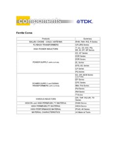
3 Attention to basic circuit design, compo-nent layout, shielded enclosures and other use of shieldingmaterials may be considered. For reducing or eliminatingconducted EMI on printed circuit boards in wiring and cables, Ferrite components have been used very successfully for de-cades. The Ferrite core introduces into the circuit a frequencyvariable impedance, see Figure 2. The core will not affect thelower frequency operating signals but does block the conduc-tion of the EMI noise frequencies. The Figures 3 and 4 arephotographs of a representative sampling of the Fair-RiteProducts Corp. product line of suppressor 2 Impedance, reactance, and resistance vs. frequency for a Ferrite core in 43 , RS, XL ()250200150100500 Frequency (Hz) Box J,One Commercial Row, Wallkill, NY 12589-0288 Phone:(888) FAIR RITE / (845) 895-2055 FAX:(888) Ferrite / (845) 895-2629 E-Mail: 324-7748(888) 337-7483 Note: (914) Area Code has changed to (845).Fair-Rite Products Edition175 Technical InformationFigure 3, 4 Variety of EMI Suppression Cores including: (1) Beads on Leads, (2) Split Round Cable Suppression Cores andCases, (3) Split Flat Cable Suppression Cores and Cases, (4) Printed Circuit (PC) Beads, (5) Toroidal Type Shield Beads,(6) Surface-Mount (SM) Beads, (7) on Reel, (8) Wound Beads, (9) Connector Suppression Discs and Plates and(10) One of nine Engineering Kits containing a Large Variety of Samples of EMI Suppressor MagneticsThe permeability of a Ferrite material is a complex parameterconsisting of a real and an imaginary part.
4 The real componentrepresents the reactive portion and the imaginary componentrepresents the losses. These may be expressed as seriescomponents ( s', s") or parallel components ( p', p").Figure 5 is the vector representation of the series equivalentcircuit of a Ferrite suppression core; the loss free inductor (Ls) isin series with the equivalent loss resistor (Rs). The followingequations relate the series impedance and the complex perme-ability:Z = j Ls + Rs = j Lo( s'- j s") ohmso that Ls= Lo s' ohmRs= Lo s" ohmwhere: Lo = 4 N210-9(H) is the air core impedance of a Ferrite suppressor core is a combination ofthe intrinsic material characteristics us' and us", the square of theturns and of the Ferrite core. The complex permeability compo-nents s' and s" vary as a function of frequency. The coregeometry and the number of turns are frequency independentcontributors to the overall 5 Material SelectionConducted EMI can occur over a wide range of frequencies,from as low as 1 MHz to several GHz.
5 To provide protection oversuch a wide frequency range a number of Ferrite materials willhave to be made offers a complete line of suppression ferrites that covera gamut of frequencies. Starting at 1 MHz MnZn ferrites 73 and31 are used. Beginning around 20 MHz up to 200/300 MHz theNiZn materials 43 and 44 are recommended. For the highestfrequencies the NiZn 61 material is the Box J,One Commercial Row, Wallkill, NY 12589-0288 Phone:(888) FAIR RITE / (845) 895-2055 FAX:(888) Ferrite / (845) 895-2629 E-Mail: 324-7748(888) 337-7483 Note: (914) Area Code has changed to (845).Fair-Rite Products Edition176 Technical InformationFigures 6 through 10 show for these five suppression materialsthe complex permeabilities 's and "s as a function of all these materials at low frequencies 's is highest but as thefrequency increases "s becomes the dominant material param-eter whence the biggest contributor to the overall impedance. Atthe low frequencies where 's is highest the suppression core ismostly inductive and rejects EMI signals.
6 At the higher frequen-cies where "s becomes the more significant parameter theimpedance will become more and more resistive and absorbs theconducted 1 lists Fair-Rite s suppression materials, suggested oper-ating frequency ranges and the test frequencies for the fivesuppression materials. The recommended materials will providethe highest combination of the primary material characteristics 's and "s over that frequency 1 MaterialFrequency RangeTest FrequenciesComments73 1 25 MHz 10 25 MHz Small parts only31 1 300 MHz 10 25 100 MHzLarge parts only43 20 300 MHz 25 100 MHzWide range of parts44 20 300 MHz 25 100 MHzHigh resistivity61 200+ MHz100 250 MHzFor VHF designsMaking the material selection is the first step in eliminatingconducted EMI problems. To make this material selection it isimperative that the frequency or frequencies of the unwantednoise are known. This needs not be an exact figure; an approxi-mation will be sufficient.
7 From the EMI frequency the material canbe selected. It should be made clear that several environmentalconditions will have to be addressed before this selection be-comes ConditionsAs shown in Figures 6 through 10, the 's and "s will vary as afunction of frequency. However, several environmental condi-tions will also affect these primary material parameters. The mostsignificant ones are temperature and dc in the combination of 's and "s due to temperature isstrictly a material characteristic which is not affected by the coregeometry. The graphs in Figures 11 through 15 show the per-centage change in impedance as a function of temperature whencompared to room temperature. These typical changes in imped-ance will be applicable for all components made from thesematerials. Designers can use these graphs to evaluate perfor-mance of specific components versus (Hz)104105106107108 Figure 6 Complex Permeability vs. FrequencyMeasured on a 2673000301 bead using the HP 4284A and the HP 7 Complex Permeability vs.
8 FrequencyMeasured on a 17/10/6mm toroid using the HP 4284A and the HP (Hz)10510610710873 Material31 Box J,One Commercial Row, Wallkill, NY 12589-0288 Phone:(888) FAIR RITE / (845) 895-2055 FAX:(888) Ferrite / (845) 895-2629 E-Mail: 324-7748(888) 337-7483 Note: (914) Area Code has changed to (845).Fair-Rite Products Edition177 Technical InformationThe dc bias is more complex. The dc bias will affect both the 'sand "s, but this is also influenced by the core geometry, specifi-cally the magnetic path length. Therefore Fair-Rite provides dcbias Information based on a dc H field in oersted for many of itssuppression components. For all EMI suppression beads andround cable suppression cores listed in the catalog a calculatedH value (H= ) that is based on a single turn and one Ampdirect current is shown. This calculated value of H should bemodified if more turns are used or if the current is not 1 A. A 2 Ampcurrent will of course double the value listed for the part.
9 Once thetrue dc H field is calculated, graphs in Figures 16 through 20 willprovide the change in impedance Information for the appropriatematerial, frequency and true H bias curves are included in this catalog for wound andassembled parts as well as for those components for which themagnetic path length cannot be easily calculated. For instance,refer to the product sections for beads on leads, pages 29-40 andchip beads, pages 50-73 . For each individual component animpedance vs. frequency curve with the dc bias as a parameteris included. Again, this will provide the designer with a quickevaluation on how the dc affects the performance of 8 Complex Permeability vs. FrequencyMeasured on a 17/10/6mm toroid using the HP 4284A and the HP (Hz)105106107108 Figure 9 Complex Permeability vs. FrequencyMeasured on a 17/10/6mm toroid using the HP 4284A and the HP (Hz)1051061071081101001000 Figure 10 Complex Permeability vs. FrequencyMeasured on a 17/10/6mm toroid using the HP 4284A and the HP (Hz)10610710810943 Material 61 Material44 Box J,One Commercial Row, Wallkill, NY 12589-0288 Phone:(888) FAIR RITE / (845) 895-2055 FAX:(888) Ferrite / (845) 895-2629 E-Mail: 324-7748(888) 337-7483 Note: (914) Area Code has changed to (845).
10 Fair-Rite Products Edition178 Technical InformationFigure 11 Percent of Original Impedance vs. TemperatureMeasured on a 2673000301 using the HP4291A. Temperature(oC)0255075100125-40 -20020406080 100 120 14025 MHz10 MHz(%)Figure 12 Percent of Original Impedance vs. TemperatureMeasured on a 2631000301 using the (oC)-40-20020406080100 12010 MHz25 MHz100 MHz50 MHz(%)Figure 13 Percent of Original Impedance vs. TemperatureMeasured on a 2643000301 using the (oC)0255075100125-40 -20020406080 10012025 MHz100 MHz50 MHz(%)Figure 14 Percent of Original Impedance vs. TemperatureMeasured on a 2644000301 using the (oC)-40-20020406080100 12025 MHz100 MHz50 MHz(%)31 Material44 Material73 Material43 Box J,One Commercial Row, Wallkill, NY 12589-0288 Phone:(888) FAIR RITE / (845) 895-2055 FAX:(888) Ferrite / (845) 895-2629 E-Mail: 324-7748(888) 337-7483 Note: (914) Area Code has changed to (845).Fair-Rite Products Edition179 Technical InformationSecondary Material ParametersAlthough 's and "s are the most critical material characteristicsfor suppression applications, resistivity and Curie temperatureare Ferrite material parameters that should be considered as Curie temperature is the transition temperature above whichthe Ferrite loses its magnetic properties.