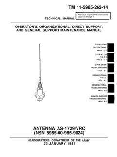
Transcription of Technical Manual Organizational Maintenance …
1 TM 9-2320-280-20. HOW TO USE THIS Manual . 1 ABOUT YOUR Manual 1. a. Spend some time looking through this Manual . You'll find that it has a new look, different than most of the TMs you've been using. New features added to improve the convenience of this Manual and increase your efficiency are: 1. Accessing Information - These include physical entry features such as the bleed-to-edge indicators on the cover and edge of the Manual . Extensive troubleshooting guides for specific systems lead directly to step by step directions for problem solving and Maintenance tasks. 2. Illustrations- A variety of methods are used to make locating and fixing components much easier. Locator illustrations with keyed text, exploded views, and cut-away diagrams make the information in this Manual easier to understand. 3. Keying Text With Illustrations- Instructions are located together with figures that illustrate the specific task you are working on.
2 In most cases, the task steps and figures are located side by side making part identification and procedure sequence easier to follow. -!l'heTM is the fundamental means by which the Army communicates to soldiers the requirements and procedures necessary to perform equipment operations and Maintenance . This Manual describes in detail the Organizational Maintenance prescribed by the Maintenance Allocation Chart (appendix B). and Source, Maintenance , and Recovery (SMR) codes (TM Q-2320-280-20P). b. General Features. Your TM is the best source available for providing information and data critical to vehicle operation and Maintenance : . Safety summary (warning page a, b, and c).. General information, equipment descriptions, and data (chapter 1).. Principles of operation (chapter 1, section III).. Preventive Maintenance Checks and Services - PMCS (chapter 2, section III).. Systems Troubleshooting (chapter 2, sections IV and V).
3 Detailed Maintenance procedures (chapters 3-12).. General Maintenance instructions (chapter 2, section II and III).. Maintenance Allocation Chart - MAC (appendix B).. Expendable/durable supplies and materials list (appendix C).. Manufactured items (appendix D).. Torque limits (appendix E).. Wiring Diagrams and Schematic (appendix F). A typical example of how to use this Manual is provided on the following pages. TM 9-2320-280-20. USING YOUR Manual : AN EXAMPLE. ARMY TM 9-2320-280-20. AIR FORCE TO 36A12-lA-2092-1. MARINE CORPS TM 2320-20/7. a. TASK: The operator of an M998 series Technical Manual . vehicle has complained that his TOW carrier Organizational Maintenance . uses too much engine oil. The vehicle has been assigned to you for repair. b. TROUBLESHOOTING STEPS: 1. Look at the cover of this Manual . You'll see chapter titles listed from top to bottom on the right-hand side.
4 2. Look at the right edge of the Manual . On some of the pages you'll see black bars (bleed-to-edge indicators) that are alined DEPARTMENTS OF THE ARMY, THE AIR FORCE, with the chapter bars on the cover. These AND HEADQUARTERS, MARINE CORPS. are the locations of the chapters in the text. 1. 3. Look for SERVICE AND TROUBLESHOOTING INSTRUCTIONS in the chapter list on the cover. This is where the troubleshooting information is located. 4. Turn to those pages with the edge indicator matching the black bar for service and troubleshooting instructions. Page numbers are also listed next to chapter titles. 5. Chapter 2 is divided into six sections: l Section I - Repair Parts, Special Tools, TMDE, and Support Equipment l Section II - Service Upon Receipt l Section III - PMCS. l Section IV - Mechanical Systems Troubleshooting l Section V - Electrical Systems Troubleshooting l Section VI - STE/ICE Troubleshooting TM 9-2320-280-20.
5 6. Turn to section IV, MECHANICAL. SYSTEMSTROUBLESHOOTING(page 2- 12). This troubleshooting section is system-oriented and is broken down into 11 major vehicle systems. One of the first pages of this section is the MECHANICALTROUBLESHOOTING. SYMPTOMINDEX (turn to page 2-13). Look down the list of symptoms until you find ENGINE .Beneath that heading you will find the symptom noted by the vehicle operator as Malfunction No. 5: Excessive oil loss or consumption . Turn to the page indicated: 2-16. vii TM 9-2320-280-20. 10. On page 2-16, steps relating to resolving the problem of excessive oil loss are listed. Read down the page until you find EXCESSIVE OIL LOSS OR CONSUMP- TION . The steps listed are shown in the example page to the right of this text. 11. In accordance with the NOTE , you start the engine and watch the exhaust for signs of excessive smoke that might indicate that the engine is burning oil.
6 The exhaust appears normal and you move on to Step 1. 12. In Step 1, you begin a methodical check of the engine lubricating system. You discover a leak in the oil cooler assembly adjacent to one of the mounting brackets. One of the welds has cracked, allowing a class III leak from a small area of the cooling fins. The oil cooler assembly must be replaced or repaired. 13. At this point, some malfunction/test steps in table 2-2 Mechanical Systems Troubleshooting would direct you to a specific detailed procedure to solve the problem. However, the engine lubricating system is complex and you must now refer to the table of contents. NOTE: Refore attempting to repair or replace the oil cooler assembly, as an Organizational mechanic, you must: a. Determine the Maintenance responsibility of repair or replacement of the component. b. If the task is at your echelon of Maintenance responsibility, you must identify the tools needed and the replacement parts required.
7 Refer to the Maintenance Allocation Chart - MAC (appendix B) to determine not only the Maintenance responsibility of the item, but also to obtain an estimate of the time required to perform the task, tools needed, and any special notes/requirements necessary. Refer to TM 9-2320-280-2OP, Organizational Maintenance Repair Parts and Special Tools List for M998. Series Vehicles, for requisition data concerning replacement parts for this task.. VIII. TM 9-2320-280-20. c. OIL COOLER ASSEMBLY REPLAC'E- MENT. After reporting the results of your troubleshooting efforts to your supervisor, he decides that the most expedient means of returning the vehicle to service would be to replace the oil cooler assembly. 1. Turn to the TAHLE OF CONTENTS and find the chapter dealing with the engine. You find it as CHAF'TER 3, ENGINE. SYSTEMS Maintenance . Further- more, you note that the chapter is divided into five sections; you are interested in Section I.
8 Lubrication System . 2. Turn to Chapter 3, section I on page 3-l. Here you find the Lubrication System Maintenance Task Summary . Read down the list of tasks until you find the one that will correct your Maintenance problem. For our example, you find it as task 3-7 Engine and Transmission Oil Cooler Assembly Replacement . Turn to page 3-12. ix TM 9-2320-280-20. [ 3-7. ENGINE AND TRANSMISSION OIL COOLER ASSEMBLY REPLACEMENT ) 3-7. ENGINE AND TRANSMISSION 011 COOLER ASSEMBLY. REPLACEMENT (Cont'd). 3. On page 3-12 you find paragraph 3-7, the detailed procedure for replacing the oil cooler assembly. d. DETAILED Maintenance PROCEDURES. Detailed Maintenance procedures include everything you must do to accomplish a basic Maintenance task. 1. Before beginning the Maintenance task, look through the procedure. You must familiarize yourself with the entire Maintenance procedure of para.]
9 3-7: Engine and Transmission Oil Cooler Assembly Replacement . The task includes a. Removal and b. Installation . 2. The eight basic headings listed under INITIAL SETUP outline task conditions, materials, special tools, manpower requirements, and special conditions. The headings are: Applicable Models: Any models that require a particular Maintenance task. If a Maintenance task covers all models, then this heading will not be used. Test Equipment: Test equipment needed to complete a task. If test equipment is not required, this heading will not be used. Special Tools: Those special tools needed to complete a Maintenance task. The use of common tools is not explained. If no special tools are needed, this heading will not be used. If you don't have one of these special tools, requisition it (before startivg the task) using the data supplied in TM 9-2320-280-2OP, the repair parts and special tools list for this level of Maintenance .
10 Special tools are located in section III. Materials/Parts: This heading lists only mandatory replacement materials or parts (gaskets, 0 rings, sealant, etc.). To replace other unserviceable parts, refer to TM 9-2320-280-20P for requisition data. If no mandatory replacement materials/parts are required, this heading will not be used. TA 266712. X. TM 9-2320-280-20.. Personnel Required: The number of personnel needed to perform a task. If only one mechanic is needed, this heading will not be used. NOTE. If you think that you need more help to adequately or safely complete a task, perhaps as the result of unusual conditions, etc., alert your supervisor and ask for help.. Manual References: Those TMs needed to complete the task. l Equipment Condition: Notes the conditions that must exist before starting the task. If none are required, this heading will not be used. For oil cooler assembly replacement, the left-hand engine splash shield should be removed before we can start the task.