Transcription of TECHNICAL SERVICE MANUAL - Viking
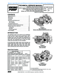
1 SECTION TSM 1 OF 19 ISSUE LTECHNICAL SERVICE MANUAL CONTENTSINTRODUCTIONThe illustrations used in this MANUAL are for identification purposes only and cannot be used for ordering parts. Due to the nature of the pump and the close manufacturing tolerances, certain replacement parts are only available in assemblies. Instructions given are for replacing the pump or coupling parts, or entire pumping unit. Always give name of part, model and serial number of the pump when ordering repair parts. The pump model and serial number can be found on the nameplate secured to the pump. In the Viking model number system, the first number 8 indicates a magnetically coupled design. The next two numbers determine the series size and the last two numbers indicate the gear length. SG Series pumps have cast iron construction. SGN pumps feature ductile iron external MANUAL deals with Model SG-804, SG-805 & SG-807 pumps mounting on the magnetic drive MD-A4, MD-A9, MD-B15 and MD-B40 couplings, as well as Model SG-810 & SG-814 pumps mounting on the magnetic drive MD2-B & MD2-C couplings.
2 Refer to Figures 1 through 26 for general configuration and nomenclature used in this MANUAL . Pump specifications and recommendations are listed in Catalog Section 1SG-80514 MD-A4 MMotor Direct Connected To Footless Bracket & PumpFIGURE 2SG-80711 MD-A9B & Mounted Pump(Counterclockwise Rotation Shaft)MAGNETIC DRIVE - CAST IRON & DUCTILE IRON PUMPS SERIES SG & SGNSIZES 804, 805, 807, 810 & 814 Introduction .. 1 Safety Information & Information .. 3 Health Concerns .. 3 Installation .. 3 Start Up .. 5 Maintenance .. 5MD-A & MD-B Coupling Pump Removal .. 7SG-804, -805 & -807 Pump 9SG-804, -805 & -807 Pump 9MD-A & MD-B Coupling Assembly .. 10MD2-B & MD2-C Coupling Pump Removal .. 11SG-810 & SG-814 Pump 12MD2-B Coupling Disassembly .. 14MD2-C Coupling 14SG-810 & SG-814 Pump 14 Installation of Carbon Graphite Bushings .. 14 Assembly of Coupling - Series MD2-B & MD2-C .. 14MD2-B Bearing Carrier 15MD2-C Bearing Carrier Assembly .. 15 Pressure Relief Valve Instructions.
3 16 Troubleshooting .. 16Do s and Don ts .. 17 Maintenance .. 18 Warranty .. 19 UNMOUNTED PUMPUNITSCAST IRONDUCTILE IRONU nits are designated by the unmounted pump model number followed by the magnetic coupling size and letter indicating the drive style - Direct DriveM - Motor Mounted (Close Coupled C-Flange)B - Bearing Carrier MountedR - Viking Reducer DriveP - Commercial Reducer Drive(Example: SG-80514-MD-A4 B)SG-80417-SG-80418-SG-80425-SG-80435-SG -80450-SG-80470-SG-80518 SGN-80518SG-80525 SGN-80525SG-80535 SGN-80535SG-80550 SGN-80550SG-80570 SGN-80570SG-80510 SGN-80510SG-80514 SGN-80514SG-80519 SGN-80519SG-80528 SGN-80528SG-80741 SGN-80741SG-80758 SGN-80758SG-80782 SGN-80782SG-80711 SGN-80711SG-80716 SGN-80716SG-80722 SGN-80722SG-80732 SGN-80732SG-81009-SG-81013-SG-81026-SG-8 1420-SG-81436-SG-81456-MODEL NUMBER CHART:Electronic copies of the most current TSM issue can be found on the Viking Pump website at PUMP, INC.
4 A Unit of IDEX Corporation Cedar Falls, IA 50613 USASECTION 2OF 19 BEFORE opening any liquid chamber (pumping chamber, reservoir, relief valve adjusting cap fitting, etc.) be sure that : Any pressure in the chamber has been completely vented through the suction or discharge lines or other appropriate openings or connections. The pump drive system means (motor, turbine, engine, etc.) has been locked out or otherwise been made non-operational so that it cannot be started while work is being done on the pump. You know what material the pump has been handling, have obtained a material safety data sheet (MSDS) for the material, and understand and follow all precautions appropriate for the safe handling of the operating the pump, be sure all drive guards are in NOT operate pump if the suction or discharge piping is not connected. DO NOT place fingers into the pumping chamber or its connection ports or into any part of the drive train if there is any possibility of the pump shafts being NOT exceed the pump s rated pressure, speed, temperature, or change the system/duty parameters from those the pump was originally supplied, without confirming its suitability for the new operating the pump, be sure that: It is clean and free from debris all valves in the suction and discharge pipelines are fully opened.
5 All piping connected to the pump is fully supported and correctly aligned with the pump. Pump rotation is correct for the desired direction of pressure gauges/sensors next to the pump suction and discharge connections to monitor extreme caution when lifting the pump. Suitable lifting devices should be used when appropriate. Lifting eyes installed on the pump must be used only to lift the pump, not the pump with drive and/or base plate. If the pump is mounted on a base plate, the base plate must be used for all lifting purposes. If slings are used for lifting, they must be safely and securely attached. For weight of the pump alone (which does not include the drive and/or base plate) refer to the Viking Pump product NOT attempt to dismantle a pressure relief valve that has not had the spring pressure relieved or is mounted on a pump that is contact with hot areas of the pump and/or drive.
6 Certain operating conditions, temperature control devices (jackets, heat-tracing, etc.), improper installation, improper operation, and improper maintenance can all cause high temperatures on the pump and/or PUMP must be provided with pressure protection. This may be provided through a relief valve mounted directly on the pump, an in-line pressure relief valve, a torque limiting device, or a rupture disk. If pump rotation may be reversed during operation, pressure protection must be provided on both sides of pump. Relief valve adjusting screw caps must always point towards suction side of the pump. If pump rotation is reversed, position of the relief valve must be changed. Pressure relief valves cannot be used to control pump flow or regulate discharge pressure. For additional information, refer to Viking Pump s TECHNICAL SERVICE MANUAL TSM 000 and Engineering SERVICE Bulletin PUMP must be installed in a matter that allows safe access for routine maintenance and for inspection during operation to check for leakage and monitor pump INFORMATION AND INSTRUCTIONSD anger - Failure to follow the indicated instruction may result in serious injury or - In addition to possible serious injury or death, failure to follow the indicated instruction may cause damage to pump and/or other INSTALLATION, OPERATION OR MAINTENANCE OF PUMP MAY CAUSE SERIOUS INJURY OR DEATH AND/OR RESULT IN DAMAGE TO PUMP AND/OR OTHER EQUIPMENT.
7 Viking S WARRANTY DOES NOT COVER FAILURE DUE TO IMPROPER INSTALLATION, OPERATION OR INFORMATION MUST BE FULLY READ BEFORE BEGINNING INSTALLATION, OPERATION OR MAINTENANCE OF PUMP AND MUST BE KEPT WITH PUMP. PUMP MUST BE INSTALLED, OPERATED AND MAINTAINED ONLY BY SUITABLY TRAINED AND QUALIFIED FOLLOWING SAFETY INSTRUCTIONS MUST BE FOLLOWED AND ADHERED TO AT ALL :!!!!!WARNING!!!WARNING!WARNING!WARNING! WARNING!SECTION 3OF 19 CAUTION !Rare earth magnets used in these couplings have extremely strong magnetic fields capa-ble of changing the performance or damaging items such as the following: Pacemakers Metal implants Watches Computers and discs Credit cardsCompletely assembled magnetic couplings will not affect the items listed performance or damage can occur only when the coupling halves are are no known harmful effects of these magnetic fields on the human body following items must be considered prior to pump installation:1.
8 Location - locate the pump as close as possible to supply of liquid being pumped. If possible locate the pump below liquid supply. Viking pumps are self priming; but, the better the suction conditions the better the pump will Accessibility - pump must be accessible for inspection, maintenance and INFORMATIONROTATION: Viking Mag Drive pumps are designed to run in a designated direction (indicated on name plate). Shaft rotation determines which port is suction and which is discharge. Running the pump in the opposite direction may seriously affect the performance of the unit and the relief valve (if present) will not operate. If rotation must be reversed, contact your Viking Pump supplier for instructions and parts to change A pressure relief valve is mounted as standard on the SG/SGN series magnetically coupled The SG/SGN series is a positive displacement pump and requires some form of over pressure protection.
9 Without pressure protection, if the discharge line is blocked or becomes closed, pressure will build up until the motor stalls, drive equipment fails, a pump part breaks, or the piping and/or other equipment in the system may be an integral pressure relief valve supplied with the pump, a torque limiting device or a rupture Do not use decoupling of magnets as protection from over pressure. SG/SGN Series pumps can develop potentially damaging pressure before the magnets decouple. Decoupling of the magnets may also cause damage to the magnets The relief valve adjusting screw cap must always point toward suction side of Pressure relief valves cannot be used to control flow or regulate additional information on pressure relief valves. Refer to TECHNICAL SERVICE MANUAL TSM000 and Engineering SERVICE Bulletin !Before opening any Viking pump liquid chamber (pumping chamber, reservoir, relief valve adjusting cap fitting etc.)
10 Be sure:1. That any pressure in the chamber has been completely vented through the suction or discharge lines or other appropriate openings or That the driving means (motor, turbine, engine, etc.) has been locked out or made non- operational so that it cannot be started while work is being done on pump. 3. That you know what liquid the pump has been handling and the precautions necessary to safely handle the liquid. Obtain a material safety data sheet (MSDS) for the liquid to be sure these precautions are to follow above listed precautionary measures may result in serious injury or - 81013 - M 0 V USpur Gear PrincipleDesign SeriesBracket:M = Metric (ISO) Bracket for IEC Motor Mount (-10,-14)U = SAE Bracket for NEMA Motor Mount (-10,-14)Relief Valve:O = Without ValveV = With Valve(Single Pumps only)Shaft Rotation:(Viewed from shaft end)0 = Clockwise1 = Counter-ClockwiseSeal Type:8 = Mag DriveMaterial of Construction:Blank = Cast Iron N = Ductile Iron (-805,-807)Frame SizePump SizeSDSDSDUSE STRAIGHT EDGE.