Transcription of TECHNICAL SERVICE MANUAL - Viking Pump Canada
1 BULLETIN TSM-000-V PAGE 1 OF 9 ISSUE E. 12/2007 TECHNICAL SERVICE MANUALINSTALLATION, START-UP, TROUBLESHOOTING, PREVENTATIVE MAINTENANCE, DO S AND DON TS Viking PUMP Box 398, 661 Grove Ave. Windsor, Ontario, N9A 6M3, Canada 5. Pressure Protection - Viking pumps are positive displacement. This means that when the pump is rotated, liquid will be delivered to the discharge side of the pump. If there is no place for this liquid to go - discharge line is blocked or closed - pressure can build up until the motor stalls, the drive equipment fails, a pump part breaks or ruptures, or the piping bursts.
2 Because of this, some form of pressure protection must be used with a positive displacement pump. This may be relief valve mounted directly on the pump, an inline relief valve, a torque limiting device or a rupture disk. The pressure relief valve mounted on Viking pumps and most in-line valves are of the spring loaded poppet design See Figure 4. The spring (A) holds poppet (B) against the seat in the valve body (C) with a given force determined by the spring size and by how tightly it is compressed by the adjusting screw (D). The pump discharge pressure pushes against the underside of the poppet at point (E).
3 When the force exerted by the liquid under the poppet exceeds that exerted by the spring, the poppet lifts and liquid starts to flow through the valve. CONTENTS Installation, General Comments Foundation Alignment Piping Start Up Troubleshooting Preventative Maintenance Rapid Wear Do s and Don ts Warranty GENERAL Before installation is started a few items of a general nature should be considered. 1. Location - always locate the pump as close as possible to the supply of liquid to be pumped. Locate it below the liquid supply if at all practical. Viking pumps are self priming but the better the suction conditions the better the performance.
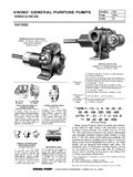
4 2. Accessibility - the pump should be located where it is accessible for inspection, maintenance, and repair. For large pumps , allow room to remove the rotor and shaft without removing the pump from the base. 3. Port Arrangement - since the pumps have different port arrangements depending on the model, port location should be checked before starting the installation. The ports may be upright, opposite or at right angles to each other, see Figure 1. The right angle ports are normally right-hand, see Figure 2; some models are available with left-hand arrangements; still other models are available with the right angle ports located in any one of eight positions including right-hand and left-hand.
5 1 2 3 3 4 5 6 7 8 9 4. Suction/Discharge - shaft rotation will determine which port is suction and which discharge. A look at Figure 3 will show how rotation determines which port is which; as the pumping elements (gears) come out of mesh, point "A" on Figure 3, liquid is drawn into the suction port; as the gears come into mesh, point "B", the liquid is forced out the discharge port. Reversing the rotation reverses the flow through the pump. When determining shaft rotation, always look from the shaft end of the pump. Unless otherwise specified, rotation is assumed to be clockwise (CW), which makes the suction port on the right side of the pump.
6 The idler pin, which is offset in the pump head, should be properly positioned toward and an equal distance between the port connections. IDLER PIN B DISCHARGE SUCTION A FIGURE 3 LEFT HAND PUMP RIGHT HAND PUMP FIGURE 1 FIGURE 2 ADJUSTING SCREW (D) LIQUID INLET LIQUID OUTLET POINT (C) POPPET (B) VALVE BODY (C) CAP SHOULD ALWAYS POINT TOWARD SUCTION PORT SPRING (A) PUMP HEAD DISCHARGE ADJUSTING SCREW CAP (SHOULD ALWAYS POINT TOWARD SUCTION PORT) SUCTION CUT-AWAY OF MAGNUS INTERNAL RELIEF VALVE FIGURE 4 FIGURE 5A INTERNAL RELIEF VALVE CAUTION INTERNAL TYPE RELIEF VALVES MOUNTED ON Viking pumps SHOULD ALWAYS HAVE THE CAP OR BONNET POINTED TOWARD THE SUCTION SIDE OF THE PUMP.
7 RETURN-TO-TANK-TYPE RELIEF VALVES SHOULD ALWAYS BE MOUNTED ON THE DISCHARGE SIDE OF THE PUMP. IF PUMP ROTATION IS REVERSED, CHANGE THE RELIEF VALVE. TURN THE INTERNAL TYPE END FOR END; MOVE THE RETURN-TO-TANK TYPE TO THE OTHER PORT. IF, ON A PARTICULAR INSTALLATION ROTATION IS REVERSED, , USING ONE PUMP TO FILL A TANK AND THEN BY USE OF A REVERSING SWITCH OR OTHER MEANS CHANGING THE ROTATION TO PERMIT THE SAME PUMP TO CIRCULATE THE LIQUID THROUGH A HEATER OR TO LOAD OUT) THEN PRESSURE PROTECTION MUST BE PROVIDED ON BOTH SIDES OF THE PUMP OR FOR BOTH ROTATIONS.
8 THIS MAY BE A COMBINATION OF RELIEF VALVES, TORQUE LIMITING DEVICES OR RUPTURE DISKS. PUMP HEAD VALVE ALWAYS MOUNTS ON THE DISCHARGE SIDE OF THE PUMP SUCTION DISCHARGE FIGURE 5B RETURN-TO-TANK RELIEF VALVE NOTE: on some models the relief valve is mounted on the pump casing instead of the pump head. The spring loaded poppet-type valve is strictly a differential valve, sensing only those pressures on each side of the poppet. It should not be used as a pressure or flow control device. It is intended strictly as a relief valve. The pressure at which either the return-to-tank or internal relief valve bypasses can be changed by turning the adjusting screw.
9 Do not back the adjusting screw all the way out. Stop when spring tension is off the screw (the screw starts to turn easily). For details on maintenance of the relief valve see TECHNICAL SERVICE MANUAL covering your model series. 6. Motor - follow local electrical codes when booking up motors. FOUNDATION Every pump should have a solid foundation. It may be any structure sufficiently strong to hold the pump rigid and to absorb any strain or shock that may be encountered. A certified print of the pumping unit should be used in preparing the foundation. If a separate foundation is provided, make it at least four inches wider and longer than the base of the unit.
10 When the unit is placed on the foundation it should be leveled and checked for position against the piping layout and then fastened down. BULLETIN TSM-000-VISSUE E PAGE 2 OF 9 pumps OR SYSTEMS WITHOUT RELIEF VALVES SHOULD HAVE SOME FORM OF PRESSURE PROTECTION, , TORQUE LIMITING DEVICES OR RUPTURE DISKS. Viking pumps can be furnished with either an internal relief valve - one which directs the flow from the valve back to the suction side of the pump - or a return-to-tank valve which directs the flow through piping back to the supply tank. See Figure 5.