Transcription of TECHNICAL SUPPORT MANUAL Two--Stage Split System …
1 428 04 1701 00 April 2012 TECHNICAL SUPPORT MANUALTwo-- stage Split System Heat Pump(H,C,T)CH6 DANGER, WARNING, CAUTION, andNOTEThe signal wordsDANGER, WARNING,CAUTION,andNOTEare used to identify levels ofhazard seriousness. The signal wordDANGER isonly used on product labels to signify an immediatehazard. The signal wordsWARNING, CAUTION,andNOTE will be used on product labels andthroughout this MANUAL andother manuals that mayapply to the Immediate hazards whichwillresult insevere personal injury or Hazards or unsafe practices whichcouldresult in severe personal injury or Hazards or unsafe practices whichmayresult in minor personal injury or product orproperty Used to highlight suggestions whichwillresult in enhanced installation, reliability, Words in ManualsThe signal wordWARNINGis used throughout thismanual in the following manner:The signal wordCAUTIONis used throughout thismanual in the following manner:Signal Words on Product LabelingSignal words are used in combination with colorsand/or pictures on product Labeling and Signal Words!
2 !CAUTIONWARNINGTABLE OF CONTENTSM odel Number Quick Reference Diagram Diagram Charging Labels (Expanded Data) Multiplying Multiplying ,CCH6,TCH6 Parts !WARNINGPERSONAL INJURY, AND/OR PROPERTY DAM-AGE HAZARDF ailure to carefully read and follow this warningcould result in equipment malfunction, propertydamage, personal injury and/or or repairs made by unqualified per-sons could result in equipment malfunction,prop-erty damage, personal injury and/or information contained in this MANUAL is in-tended for use by a qualified service technician fa-miliar with safety procedures and equipped withthe proper tools and test must conform with local buildingcodes and with the National Electrical CodeNFPA70 current edition or Canadian ElectricalCode Part 1 CSA SUPPORT MANUALS plit System Heat Pump: (H,C,T)CH(6)2428 04 170100 OUTDOOR UNIT MODEL NUMBER IDENTIFICATION GUIDE (single phase)Digit Position:12345, 6789101112 Example Part Number.
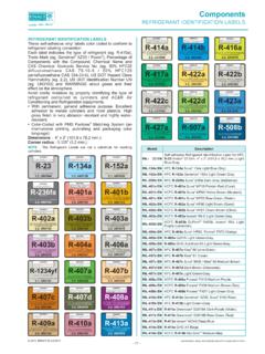
3 HCTCH624 GKA100T = Tempstar MainlineH = Arcoaire MainlineC = Comfortmaker MainlineC = Day & Night MainlineH = Airquest MainlineC = Keeprite MainlineC = Kenmore MainlineH = Kenmore MainlineT = Kenmore MainlineH = ICP Commercial MainlineH = Heil MainlineN = Tempstar EntryBRANDINGN = Arcoaire EntryBRANDINGN = Comfortmaker EntryBRANDINGN = Day & Night EntryBRANDINGN = Airquest EntryBRANDINGN = Keeprite EntryBRANDINGN = Kenmore EntryBRANDINGN = Kenmore EntryBRANDINGN = Kenmore EntryBRANDINGN = ICP Commercial EntryBRANDINGC = CommunicatingKEY CHARACTERISTICA = Air ConditionerH = Heat PumpTYPE6 = 16 SEER7 = 17 SEER8 = 18 SEER9 = 19 SEERNOMINAL EFFICIENCY24 = 24,000 BTUH = 2 tons36 = 36,000 BTUH = 3 tons48 = 48,000 BTUH = 4 tons60 = 60,000 BTUH = 5 tonsNOMINAL CAPACITYG = Coil Guard GrilleFEATURESK = 208/230--1--60 VOLTAGES ales CodeEngineering RevisionExtra DigitExtra DigitTECHNICAL SUPPORT MANUALS plit System Heat Pump: (H,C,T)CH(6)428 04 1701003 ACCESSORIES PART NUMBER IDENTIFICATION GUIDED igit Position:123456, 78, 910, 11 Example Part Number:NASA00101 CHN = Non--BrandedA = AccessoryPRODUCT GROUPS = Split System (AC & HP)KIT USAGEA = OriginalB = 2nd GenerationMAJOR SERIES0 = Generic or Not Applicable2=R--224 = R--410 AREFRIGERANTP roduct Identifier NumberPackage QuantityType of Kit (Example: CH = Crankcase Heater) TECHNICAL SUPPORT MANUALS plit System Heat Pump: (H,C,T)CH(6)4428 04 170100R--410A QUICK REFERENCE GUIDE R--410A refrigerant operates at 50% -- 70% higher pressures than R--22.
4 Be sure that servicing equipment andreplacement components are designed to operate with R--410A. R--410A refrigerant cylinders are rose colored. Recovery cylinder service pressure rating must be 400 psig, DOT 4BA400 or DOT BW400. R--410A systems should be charged with liquid refrigerant. Use a commercial type metering device in themanifold hose when charging into suction line with compressor operating. Manifold sets should be 750 psig high--side and 200 psig low--side with 520 psig low--side retard. Use hoses with 750 psig service pressure rating. Leak detectors should be designed to detect HFC refrigerant. R--410A, as with other HFC refrigerants, is only compatible with POE oils. Vacuum pumps will not remove moisture from oil. Do not use liquid line filter--driers with rated working pressures less than 600 psig. Do not install a suction line filter--drier in liquid line. POE oils absorb moisture rapidly.
5 Do not expose oil to atmosphere. POE oils may cause damage to certain plastics and roofing materials. Wrap all filter--driers and service valves with wet cloth when brazing. A liquid line filter--drier is required on every unit. Do not use with an R--22 TXV. If indoor unit is equipped with an R--22 TXV, it must be changed to an R--410A TXV. Never open System to atmosphere while it is under a vacuum. When System must beopened for service, break vacuum with dry nitrogenand replace all filter--driers. Evacuateto 500 microns before recharging. Do not vent R--410A into the atmosphere. Do not use capillary tube indoor coils. Observe allWARNINGS,CAUTIONS, NOTES, Comfort Products, LLCL ewisburg, TN 37091 USATECHNICAL SUPPORT MANUALS plit System Heat Pump: (H,C,T)CH(6)428 04 1701005235PL54208/230 1 POWERSUPPLYEQUIP GNDL1L2 RED/WHTBRN/YELBLUVIOCOMPCCH*DEFROSTTIMEF ORCEDDEFROST23 CQUIETSHIFT1PL1PL8 CBVIOBLK BLKYELBLUPWM2 PWM1 MODEL PLUGLEDLEDCOMM STATUS12060303060 TIME(MIN)HILOCBRN/YELBLURED/WHTL2VS904C1 2345 OCTOATOCTOATPL6 BRNBRNBLKBLK132 ONOFF(DEFAULT)CBRNBLUYELTRAN24V230 VCS208 VCOMREDBRNBRNBLKBLKBLKBLKYELBLKBLKYELBLU YELYELYEL112123 23 CCBLUYEL*SCBRN*SR125 BLKCAPBLKOFMBRNHCFSCRCONTYELBLUREDSEC--1 BRNSEC--2 CAPCB*CCHCOMMCOMPCONTCAPACITORCIRCUIT BOARDCRANKCASE HEATERSYSTEM COMMUNICATIONCOMPRESSORCONTACTORLEGENDFA CTORY POWER WIRINGFACTORY CONTROL WIRINGFIELD CONTROL WIRINGFIELD POWER WIRINGCOMPONENT CONNECTIONFIELD SPLICEJUNCTIONCSDTSHPSLPS*LSOATOCTOFMRVS SCSEVSRSTATUSTRANCOMP HIGH CAP SOLENOIDDISCHARGE TEMP SWITCHHIGH PRESSURE SWITCHLOW PRESSURE SWITCHLIQUID SOLENOIDTHERMISTOR (OUTDOOR AIR)
6 THERMISTOR COILOUTDOOR FAN MOTORREVERSING VALVE SOLENOIDSTART CAPACITORSOLENOID EXPANSION VALVESTART RELAYSYSTEM FUNCTION LIGHTTRANSFORMERNOTES:1. Compressor furnished with inherent thermal To be wired in accordance with National Electric Code ( ) and local Outdoor unit control requires a minimum of 27 va, 24 vac control Use copper conductors only. Use conductors suitable for at least 70 C (167 F).5. If indoor section has a transformer with a grounded secondary, connect the grounded side to C .6. If any of the original wire, as supplied, must be replaced, use the same or equivalent Check all electrical connections inside control box for Do not attempt to operate unit until service valves have been opened (Back Seated). USE THERMOSTAT OR OBSERVER WALL CONTROL LISTED IN PRE- SALE LITERATURE In case of non--communicating indoor System disconnect factory provided wires from Dx+ and Dx-- factory provided wires to connect to W1, Y1, Y2, and O as required by installation instructions.
7 Cap orremove unused factory provided wires. If additional grounding is needed use C For communicating control * MAY BE FIELD INSTALLED*LSRVSORGORGUTILCY1Y2W1 OOPTIONALNON--COMMUNICATINGCONTROLSEE NOTE #10 UTILCY1Y2W1 OTO INDOOR UNITDx+Dx--CNOUSEPL7 GRNYELREVAS PROVIDED BYMANUFACTURERSEE NOTE #11L1 ODFCCH338749--101 REV. AModel Sizes: 24, 36, 48, 60 CONNECTION DIAGRAMTECHNICAL SUPPORT MANUALS plit System Heat Pump: (H,C,T)CH(6)6428 04 170100 LPSEQUIPGNDTRAN 24 VTRAN 230 VDEFROSTTIMEFORCEDDEFROST23C1PL1PL8 CBPWM2 PWM1 MODEL PLUGLEDLEDCOMM STATUS12060303060 TIME(MIN)12PL312PL2L1L2VS904 COCTOAT12345 OCTOATPL6 QUIETSHIFT132 ONOFF(DEFAULT)COMPONENT ARRANGEMENTCONTACTORTRANSFORMERCAPACITOR CONTROLBOARD0240360480410430451818189115 0220 MODELMODELPLUGHK70 EZSIZEMODEL PLUG CHART1--4(R1)2--3(R2)PIN RESISTANCE (K )06004718360*SC*SR125L1 COMP2111 CONTCCH*OFM230 VCCAPHCFCONTL22323 ODFSCHEMATIC DIAGRAM (LADDER FORM)SCRVIOBLK BLKYELBLUYELBLUHILOCCONTCSCREDSEC--1 BRNSEC--2 CCHDTSHPS*LSRVSUTILCY1Y2W1 OOPTIONALNON--COMMUNICATINGCONTROLSEE NOTE #10 UTILCY1Y2W1 OTO INDOOR UNITDx+Dx--CNOUSEPL7 GRNYELREVAS PROVIDED BYMANUFACTURERSEE NOTE #11235PL54338749--101 REV.
8 AModel Sizes: 24, 36, 48, 60 PIN RESISTANCE ( K) TECHNICAL SUPPORT MANUALS plit System Heat Pump: (H,C,T)CH(6)428 04 1701007 UNIT OPERATIONS hort flashes indicate the first digit in the status code, followed by long flashes indicating the second digit of the status DEFINITIONFLASH CODEFAULT DEFINITIONFLASH CODEOn, No Flash1, Pause2, PauseContinuous Flash16253132454647 StandbyLow StageHigh StageEmergency ModeSystem Communications FailureInvalid Model PlugHigh Pressure Switch TripLow Pressure Switch TripControl FaultBrown out (230V)No 230v with Call to Run5355567172737481828384 Outdoor Air Temp SensorCoil Temp SensorTemp Sensor Range ErrorLow stage Thermal CutoutHigh stage Thermal CutoutContactor ShortedContactor Open (No 230v to Comp)Low stage Thermal Lockout (4 HRS)High stage Thermal Lockout (4 HRS)Low Pressure Lockout (4 HRS)High Pressure Lockout (4 HRS)Time DelaysThe unit time delays include.
9 --Five minute time delay to start cooling operation when there is a call from the thermostat or wallControl. To bypass this feature, momentarily short and release Forced Defrost pins or hold the Cool To or Heat To button on the Observer Wall Control for 10 minute compressor re--cycle delay on return from a brown--out minute time delay to return to standby operation from last valid communication (Observer Communicating Wall Control only).--One minute time delay of outdoor fan at termination of cooling mode when outdoorambient is greater than or equal to 100 F ( C).--Fifteen second delay at termination of defrost before the auxiliary heat (W1) is second delay at termination of defrost before the outdoor fan is second compressor delay and 40 seconds outdoor fan delay when quietshift Heater--The crankcase heater is de--energized when the compressor is running. The crankcase heater is enegized when the compressor is off and the ambient is less than 42 F.
10 When the ambient temperature isbetween 65 F and 42 F the crankcase heater is energized 30 minutes after the compressorIs turned off. When the ambient is above 65 F the crankcase heater remains de--energized after thecompressor is turned control offers 5 possible defrost interval times: 30, 60, 90, 120 minutes, or AUTO. Defrost intervalsare selected by dip switches on the unit control board or by the Observer Wall Control. The ObserverWall Control selection overrides the control board dip switch defrost adjusts the defrost interval time based on the last defrost time as follows:When defrost time <3 minutes, the next defrost interval =120 defrost time 3--5 minutes, the next defrost interval =90 defrost time 5--7 minutes, the next defrost interval =60 defrost time >7 minutes, the next defrost interval =30 time selectionTECHNICAL SUPPORT MANUALS plit System Heat Pump: (H,C,T)CH(6)8428 04 170100 The control board accumulates compressor run time.