Transcription of Technician Turbocharger Guide for the 6.0LPower …
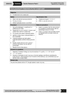
1 Technician Turbocharger Guide forthe StrokeEngineVanesVanesVGT Actuator PistonVGT Actuator PistonTurbine WheelTurbine WheelShaft SealShaft SealCompressor WheelCompressor WheelVGT Control ValveVGT Control ValveTURBOCHARGER DESCRIPTION AND BASIC OPERATIONThe Turbocharger for the Strokeengine is designed to improve throttle response byproviding boost control at low and high Variable Geometry Turbocharger (VGT) is electronically controlled by the vehicle s PCM andis hydraulically actuated using pressurized lube VGT may also be referred to as Electronic Variable Response Turbocharger (EVRT).The VGT uses a turbine wheel that is similar to a conventional Turbocharger but the turbine housing has turbine housing contains vanes that control the effectiveinternal size of the housing. These vanes are hydraulicallyactuated and electronically the vanes of the Turbocharger are closed, the enginewill have a higher exhaust back pressure and create moreheat which will in turn warm the engine faster in cold compressor on the VGT is similar to thecompressor on a conventional compressor wheel is connected to the turbine via a common shaft is supported by two (2) floating bearings.
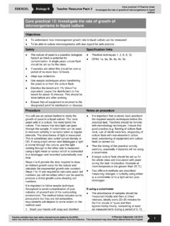
2 This bearing design uses an oil filmon the inner and outer diameter in order to create a virtual friction free HousingTurbine HousingCompressor HousingCommon ShaftCompressor WheelTurbine WheelFloating BearingsBearing Spacer1231 The VGT control valve is commanded by thePCM, based on engine speed (CKP sensor)and load (calculated value based on MFDES(Mass Fuel Desired) at a specified RPM).The PCM uses EP (Exhaust Pressure) to actas a closed loop control for the VGT and tomonitor its command can be viewed on WDS asVGT# and is described in % closed. A low %means the vanes are commanded to an openstate. A high % means the vanes arecommanded to a closed state. The magneticfield generated by this signal moves a shaft inthe control valve (VGTCV). This movementmeters engine oil through the valve to eitherside of the piston. This design feature reactsquickly to changes in demand based on driving conditions.
3 When one side of the piston is pressurized, the opposite side on which side of the piston ispressurized, the vanes either open or cam follower at the end of the valve assembly provides feedback to the valveallowing it to reach a parked position duringtimes the vanes are not commanded to the VGTCV is commanded to the fullopen position, low or no duty cycle, oil from theoil supply line is directed to the open side of theactuator on the closed side of the piston is thendirected through the hollow shaft of the actuatorpiston, back to the VGTCV, and then to : If the VGTCV is disconnected the valvewill default to the open Supply, OuterSide of PistonVanes Open PositionCoil4567 Oil Supply, InnerSide of Piston2 Cam FollowerWhen the VGTCV is commandedto the full closed position, high dutycycle, oil from the oil supply line isdirected through the actuatorpiston to the closed side of the on the open side of the pistonis directed back to the VGTCV andthen to the desired turbochargervane position is obtained, theVGTCV goes to a parked positionand both the open and closed sidesof the actuator piston are Mid PositionVanes Closed PositionCoilCoil8910113 During engine operation at low enginespeeds and load, little energy is available from the exhaust to generateboost.
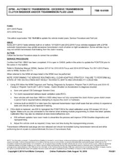
4 In order to maximize the use ofthe energy that is available, the vanesare closed. In doing so, the exhaustgas is accelerated between the vanesand across the turbine wheel increasing Turbocharger wheel speedand boost . In general, this allows theturbocharger to behave as a smallerturbocharger. Closing the vanes also increases theback pressure in the exhaust manifoldwhich is used to drive the exhaust gas through the EGR cooler and EGR valve into the intakemanifold. This is also the position for cold ambient warm Engine operation at moderate engine speeds and load,the vanes are commanded vanes are set to this intermediate position to supply thecorrect amount of boost to theengine for optimal combustion aswell as providing the necessaryback pressure for EGR : The VGT control valve piston is coupled to the vanesthrough a shaft and the engine operation at high enginespeeds and load, there is a great dealof energy available in the exhaust.
5 Excessive boost under high speed, highload conditions can negatively affectcomponent durability, therefore thevanes are commanded open preventing Turbocharger , this allows the turbochargerto act as a large Turbocharger , not creating excessive back Open PositionVanes Mid PositionActuator PistonActuator PistonVanes Closed PositionActuator Piston1213144 DIAGNOSTICSWhen diagnosing a low boost concern, verify that there is no other concern that would cause lowpower. Since boost is created by the heat of expansion, anything that can cause low power willcreate low boost (ex. injectors, EGR, exhaust leaks, fuel pressure and quality, etc.). Beforereplacing a turbo for low boost all other systems must be that MAP, BARO, EP PIDs are within PSI with Key On Engine Off (KOEO).NOTE: All values are based on a vehicle equipped with a production exhaust 2 Raise engine speed to 3500 RPM and hold it at that point while monitoring EBP_G and MGP.
6 EBP_G should be between 5 and 13 psi and MGP should be between 2 and 6 psi. If MGP and EBP_G are both high, disconnect the VGT control valve electrically and rerun thetest. If MGP and EBP_G changeinspect the wiring harness and connections. If MGP and EBP_G donotchange(lower) when VGTCV is disconnected remove the valvefrom the turbo, being careful to handle the valve by its solenoid body only, and plug it into theengine harness. Then apply pressure to the cam follower (tip of the valve) with your thumb while actuating thevalve with the WDS and look for movement. If the valve moves then proceed with Test 3, If the valve does not move replace the valve. The VGTCV (base part # 6F089) can be tested electrically, measure the resistance of theactuator coil using a DVOM, the resistance should be between & ohms @ 73 FEOT.
7 If the engine is hot the resistance should be between to ohms @ 200 F : Do not raise the engine rpm above 1200 while controlling VGT or turbo/engine damage may 1 - Checking VGT operation Using WDS in datalogger mode, highlight the RPM PID and command the engine to approximately 1200 RPM and the EGRDC# PID to 0%. Then highlight the VGTDC# and increase it to 85% and record the EBP_G (Exhaust Pressure)& MGP (Manifold Gauge Pressure). Next command the VGT to 0% and record the EBP_G and MGP PIDs. At 85% the EBP_Gshould be below PSI and MGP should be above PSI. At 0% the EBP_G should bebelow PSI and MGP should be below PSI. If it is within this range and no compressor wheel to housing contact is present then do notreplace Turbocharger . If it does not move or is not within this range then proceed to Test DisconnectedVGTCV Disconnected155If the valve is to be replaced use the following procedure:Immediately upon removal from Turbocharger , place the suspect control valve in plastic tube container provided with service kit base #6F089.
8 Handle the valve by it's solenoid body only. Donot attempt to clean or wipe oil off of valve. Do not let the valve come in contact with anythingprior to placing it in the container. This includes rags or fabric gloves that could contaminate thevalve mechanism with lint. Suspect control valve must be returned in the protective container forproper warranty credit. Note: When installing the new valve use the same caution as removal as to not contaminate the new lubricate the o-rings and install the valve into the bore. Tighten the retaining bolt to 15-18lb/ft (21-24Nm) and reconnect the electrical connector. After replacement retest the engine asstated above and if concern is still present then replace the Turbocharger #EBP_GMGPIdle60-82%0-6 psi0-1 psiWOT30-45%4-18 psi2-9 psiTest 3No-Load Boost Pressure TestRPM33003000280026002400 VGTDC#32-42%35-45%36-46%38-48%40-50%Full -Load Boost Pressure Test Road test - Select an area and appropriate transmission gear in which the vehicle can besafely operated to obtain the desired engine speed at wide open throttle.
9 Begin test at 3300 RPM and slowly apply the brake until the engine has slowed to 2400 RPM. Using WDS, select the PIDs listed below and make a 30 second recording to capture thisevent. Review the WDS recording and note the PID values at each of the specified RPM levels. If all values are within the specified range listed, the engine is operating as intended. If aspecific failure can be identified, repair as nessecary. If a failure is suspected with theturbocharger assembly then proceed to Test 4. Additional PIDs that may be helpful when diagnosing a low power complaint:APP, EGRVP, EGRDC#, ECT, EOT, ICP (voltage & pressure), ICP_DES, IPR, Load, MFDES, INJ_TIM, Fuel Pressure. EBP_DES should be 25-35 psi from 3300 to 2400 RPM under full load. EBP_G should be within 2 PSI of the EBP_DES. MGP should be 22-27 psi from 3300 to 2400 RPM under full LeaksTurbochargers have been replaced for noise concerns when the concern is exhaust mis-alignment at the connections and bad or missing gaskets.
10 There are four (4) locations nearthe Turbocharger that need to be inspected prior to replacing a Turbocharger for a noise complaint. One of these is located in the exhaust up pipe on the passenger side, there is aflange that requires a metal gasket in the pipe just above the EGR cooler connection. There isalso a metal gasket at the EGR cooler that is held in place with a V-band clamp. If the gasket ismissing, damaged or the clamp misaligned, it could be misdiagnosed as a Turbocharger other leak points are at the turbine inlet and outlet; misaligned clamps and pipes can causea noise concern. If the Turbocharger itself is responsible for excessive noise, expect to find wheelto housing rub and bearing failure. One common cause for turbo replacement is noise. A large percentage of the turbochargersreplaced for noise are not bad. Compared to the Turbocharger on the Power Stroke, theVGT is louder, under some conditions, due to increased boost and compressor speed.