Transcription of IQ Range Installation and Maintenance Instructions
1 IQ RangeInstallation andMaintenance Instructions This manual contains important safety information. Please ensure it is thoroughly read and understood before installing, operating or maintaining the of issue 10/11 The Rotork Setting Tool allows actuator control, indication and protection functions to be configured to suit site requirements. In addition, the new Setting Tool Pro also allows downloading of datalogger and uploading/downloading of configuration files. Files are transferred to and from the Setting Tool Pro via Rotork is essential that all the actuator settings are checked for compatibility with the valve, process and control system requirements before the actuator is put into service. Please read this Rotork personnel or nominated agents are contracted to carry out site commissioning and/or acceptance, documentation of commissioned actuator configuration can be made available for customer Setting Tool ProRotork Setting ToolIThis manual provides instruction on:* Manual and electrical (local and remote) operation.
2 * Preparation and Installation of the actuator onto the valve.* Subsequent commissioning and adjustment of the Basic Settings for correct valve operation.* Commissioning and adjustment of the Configuration Settings to suit site-specific control and indication requirements.* Maintenance Troubleshooting.* Sales and to Publication E180E2 for repair, overhaul andspare part ROTORK IQ Range THE FIRST VALVE ACTUATOR THAT YOU CAN COMMISSION AND INTERROGATE WITHOUT REMOVING ELECTRICAL the supplied infra-red Setting Tool to access the actuator set upprocedures, non-intrusive setting of torque levels, position limits and all other control and indication functions can be made safely, quickly andconveniently, even in hazardous locations. The IQ allows commissioningand adjustment to be carried out with the main power supply to theactuator switched on or diagnostics access information about the control system, valveand actuator status is in the form of display text and help , Alarm and Status text is available in English (default), Spanish, French and valve torque and position can be monitored on the actuatorwith a single key press of the Setting on board Datalogger captures operational and valve torque dataenabling informed Maintenance choices to be made.
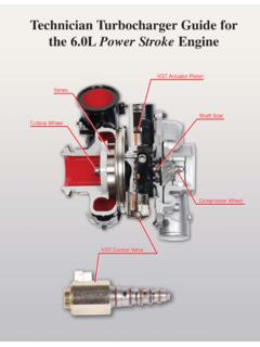
3 IQ Insight softwarefor PC and PDA allows the Datalogger to be interrogated, as well as the complete actuator set up to be configured and actuator containing the Setting Tool will be identified with a yellowlabel on the terminal our web site at for more information on the IQ, IQ Insight and other Rotork actuator Actuator PartsMotorBaseTerminal CoverHand wheelOil plugControl CoverConduit entriesOpen / Close selectorLocal / Remote / Stop selectorOil plugHand / AutoleverDisplay windowName plateBattery sealing plugMetal (8mm Allen key required)Plastic (10mm Allen key required)as nipple (if fitted)Oil plugSide hand wheelIII11 Health and Safety 2 ATEX/IEC Certified Actuators - Special Conditions 22 Storage 33 Operating your IQ Actuator 3 Operating by Hand 3 Operating Electrically 3 Display Local Indication 4 Display Status Indication Travel 5 Display Status Indication Control 5 Display Alarm Indication 54 Preparing Drive Bush 7 IQ10 to IQ35 7 Thrust Base Types A and Z IQ10 to IQ35 8 Non-Thrust Base Type B IQ40 to IQ95 8 Thrust Base Types A and Z IQ40 to IQ95 9 Non-Thrust Base Type B5 Mounting the Actuator 10 Rising Stem Valves Top Mounting 11 Valve with Gearbox Side Mounting 12 Non-Rising Stem Valves Top Mounting 12 Handwheel Sealing 12 IQM Modulating Actuators 12 IQML Linear Drive Unit
4 12 IQML Adjusting Linear Stroke 136 Cable Connections 14 Earth/Ground Connections 14 Removing Terminal Cover 14 Cable Entry 14 Connecting to Terminals 15 Replacing Terminal Cover 157 Commissioning 16 The Setting Procedure 16 The Rotork Setting Tools 17 Entering the Actuator 20 Setting Procedure Setting Mode Password 20 New Password 20 Checking Mode 20 Crossroad 21 The Actuator Display 21 Setting/Checking Mode Returning to Valve Position Display 218 Commissioning Basic Settings 22 Basic Settings Contents 239 Commissioning Configuration Settings 31 Configuration Settings Contents 33 Default Options 6310 Maintenance , Monitoring and Troubleshooting 65 Setting Tool Pro Download & Upload 68 Help Screens 71 IQ Infrared Diagnostic & Configuration 76 Environmental 7711 Weights and Measures 78 Binary, Hexadecimal and Decimal Conversion Table 7912 IQ Approvals 80 Approved Fuses 80 Maximum Flamepath Gaps 81 Appendix A 82 CONTENTSPage Page Page2 This manual is produced to enable a competent user to install, operate, adjust and inspect Rotork IQ Range valve actuators.
5 Only persons competent by virtue of their training or experience should install, maintain and repair Rotork actuators. Work undertaken must be carried out in accordance with the Instructions in this and any other relevant manuals. The user and those persons working on this equipment should be familiar with their responsibilities under any statutory provisions relating to the Health and Safety of their workplace. Due consideration of additional hazards should be taken when using the IQ Range of actuators with other equipment. Should further information and guidance relating to the safe use of the Rotork IQ Range of actuators be required, it will be provided on electrical Installation , Maintenance and use of these actuators should be carried out in accordance with the National Legislation and Statutory Provisions relating to the safe use of this equipment, applicable to the site of the UK: Electricity at Work `Regulations 1989 and the guidance given in the applicable edition of the IEE Wiring Regulations should be applied.
6 Also the user should be fully aware of his duties under the Health and Safety Act the USA: NFPA70, National Electrical Code is mechanical Installation should be carried out as outlined in this manual and also in accordance with relevant standards such as British Standard Codes of Practice. If the actuator has nameplates indicating that it is suitable for Installation in hazardous areas then the actuator may be installed in Zone 1, Zone 21, Zone 2 and Zone 22 (or Div 1 or Div 2, class I or Class II) classified hazardous area locations only. It should not be installed in hazardous area locations with an ignition temperature less than 135 C, unless suitability for lower ignition temperatures has been indicated on the actuator should only be installed in hazardous area locations compatible with the gas groups stated on the electrical Installation , Maintenance and the use of the actuator should be carried out in accordance with the code of practice relevant for that particular Hazardous Area inspection or repair should be undertaken unless it conforms to the specific hazardous area certification requirements.
7 Under no circumstances should any modification or alteration be carried out on the actuator as this could invalidate the actuators hazardous area approval certification. Access to live electrical conductors is forbidden in the hazardous area unless this is done under a special permit to work, otherwise all power should be isolated and the actuator moved to a non-hazardous area for repair or attention. WARNING: Motor TemperatureUnder normal operation the temperature of actuator s motor cover surfaces can exceed 60 C above ambient. WARNING: Thermostat BypassIf the actuator is configured to bypass the motor thermostat then the hazardous area certification will be invalidated. Additional electrical hazards may occur when using this configuration. The user should ensure that any necessary additional safety measures are considered.
8 WARNING: Control and IndicationWhere the actuator build allows remote control and indication supplies higher than 150V AC but below 300V AC (refer to actuator wiring diagram), the actuator Installation altitude must be restricted to less than 2000m as defined by BSEN 61010 or IEC 61010 (Safety Requirements For Electrical Equipment for measurement, control and laboratory use). WARNING: Enclosure MaterialsIQ10 to IQ35 are manufactured from aluminium alloy with stainless steel fasteners and the thrust bases are manufactured in cast iron. IQ40 to IQ95 enclosures are manufactured in aluminium alloy and cast iron with stainless steel fasteners and the thrust bases are manufactured in cast iron. The user must ensure that the operating environment and any materials surrounding the actuator cannot lead to a reduction in the safe use of, or the protection afforded by, the actuator.
9 Where appropriate the user must ensure the actuator is suitably protected against its operating environment. WARNING: Operating by HandWith respect to handwheel operation of Rotork electric actuators, see warning on p3. WARNING: Actuator may start and operate when remote is selected. This will be dependent on remote control signal status and actuator ATEX/IEC Certified Actuators - Special Conditions This actuator must only be located in areas where the risk of impact to the viewing window is low. Health and Safety13If your actuator cannot be installed immediately store it in a dry place until you are ready to connect incoming the actuator has to be installed but cannot be cabled it is recommended that the plastic transit cable entry plugs are replaced with metal plugs which are sealed with PTFE Rotork double-sealed construction will preserve internal electrical components perfectly if left is not necessary to remove any electrical compartment covers in order to commission the IQ cannot accept responsibility for deterioration caused on-site once the covers are Rotork actuator has been fully tested before leaving the factory to give years of trouble free operation, providing it is correctly commissioned.
10 Installed and Operating by Hand WARNINGWith respect to handwheel operation of Rotork electric actuators, under no circumstances should any additional lever device such as a wheel-key or wrench be applied to the handwheel in order to develop more force when closing or opening the valve as this may cause damage to the valve and/or actuator or may cause the valve to become stuck in the seated/backseated clear of the handwheel when engaging hand operation. Actuators driving valves via extension shafts may be subject to retained shaft torsion which can cause the handwheel to rotate when hand operation is engage handwheel drive depress the Hand/Auto lever into Hand position and turn the handwheel to engage the clutch. The lever can now be released where it will return to its original position. The handwheel will remain engaged until the actuator is operated electrically when it will automatically disengage and return to motor drive.