Transcription of Technologies, Inc Capacitors
1 Temperature compensating ceramic Capacitors are ideally suited for applications that demand controlled capacitance change with temperature variation, such as resonant circuit applications. The high capacitance in smaller packages with high reliability provides volumetric efficiency and is well-suited for automatic assembly (tape and reel). These Capacitors are suitable solutions for applications requiring: High Q and frequency stability with excellent retrace characteristics. Very predictable temperature coefficients. Capacitors unaffected by voltage, frequency, or time.
2 A dielectric material that is not ferro-electric. The most stable capacitor type available. ORDERING INFORMATION Case Size Dielectric Capacitance Tolerance Voltage Termination Packaging Hi-Reli Testing 0805 N 101 J 101 SN T - A 0402 0603 0805 1206 H: N080 J: N150 K: N220 L: N330 M: N470 N: N750 P: N1500 R: N2200 T: N3300 V: N4700 W: N5600 First 2 digits are Significant; Third digit indicates number of Zeros Examples: 201 = 200pF 2R2 = B C D F 1% G 2% J 5% K 10% M 20% First 2 digits are Significant; Third digit indicates number of Zeros Examples: 201 = 200V 151 = 150V 202 = 2000V P Palladium Silver (RoHS Compliant) S Solder Plated Over Nickel SN Tin over Nickel Plated (RoHS Compliant) G Gold over Nickel Plated (RoHS Compliant) T Tape and Reel (Optional) A = Group A B = Group B C = Group C H = Special Tested and Screened CAPAX TECHNOLOGIES, INC 24842 AVE TIBBITTS VALENCIA, CA 91355 FAX.
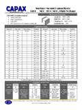
3 PAGE 1 Temperature Compensating Capacitors Technologies, Inc TEMPERATURE COEFFICIENT Refer to Table Below OPERATING TEMPERATURE RANGE - 55 C to 125 C INSULATION RESISTANCE Values to 470pF: 106 Megohms at WVDC, 25 C Values from 470 to 10,000pF: 105 Megohms at WVDC, 25 C DIELECTRIC STRENGTH times WVDC, 50 mA maximum TESTING PARAMETERS 1 KHz 50 KHz at Vrms Vrms and +25 C ENVIRONMENTAL Will meet or exceed applicable performance characteristics of MIL-PRF-55681 Dielectric Specifications Case Size 0402 0603 0805 1206 Length (L) .040 .004 ( .10) .060 .006 ( .15) .080 .008 (.)
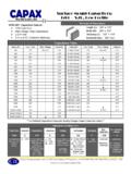
4 2) .120 .006 ( .15) Width (W) .020 .004 (.51 .10) .032 .006 (.81 .15) .050 .008 ( .10) .060 .006 ( .15) Thickness (T) .020 .004 (.51 .10) Max: .035 (Max: .889) .040 .006 ( .15) .040 .010 ( .25) Bandwidth (bw) .010 .006 (.25 .15) .014 .006 (.36 .15) .015 nom. (.38 nom) .030 nom (.76 nom) Mechanical Dimensions In Inches (millimeters) CAPAX TECHNOLOGIES, INC 24842 AVE TIBBITTS VALENCIA, CA 91355 FAX: PAGE 2 Temperature Compensating Capacitors Technologies, Inc Temperature Compensating Curves Description 0603 0805 1206 H to 150pF to 390pF 10pF to 680pF J to 150pF to 390pF 10pF to 680pF K to 220pF to 470pF 10pF to 820pF L to 220pF to 470pF 10pF to 820pF M to 270pF to 560pF 10pF to 1000pF N to330pF to 680pF 10pF to 1200pF P to 470pF to 1000pF 10pF to 1800pF R to 680pF to 1200pF 10pF to 2200pF T to 820pF to 2200pF 10pF to 3900pF V to 1800pF to 4700pF 10pF to 5600pF W to 2200pF to 5600pF 10pF to 10000pF 0402 to 82pF to 82pF to 100pF
5 To 100pF to 120pF to 150pF Capacitance Range Table % Capacitance Change 0 -60 -40 -20 0 20 40 60 80 100 120 140 -60 -40 -20 0 20 40 60 80 100 120 140 % Capacitance Change Temperature ( C) Temperature ( C) 50 40 30 20 10 0 -10 -20 -30 -40 -50 M L K J H J K L M H T V R P N T V R P N