Transcription of TERMINAL MARKINGS AND INTERNAL WIRING …
1 Service Application Manual SAM Chapter 620-37. Section 6A. TERMINAL MARKINGS AND INTERNAL WIRING diagrams single PHASE AND. polyphase MOTORS meeting NEMA standards . INTRODUCTION. The following represents the most up-to-date information on motor TERMINAL marking for proper connection to power source for all alternating current motors manufactured in accordance with standards adopted by the National Electrical Manufacturers' Association. In addition, this section contains important data covering INTERNAL WIRING to motor terminals which will prove invaluable to the Refrigeration Service Engineer in solving motor problems.
2 The source of this information is Part 2 of the NEMA standards Publication, for which reprint permission was granted RSES by the National Electrical Manufacturers' Association. MG LOCATION OF TERMINAL MARKINGS . TERMINAL MARKINGS shall be placed on or directly adjacent to terminals to which connections must be made from outside circuits or from auxiliary devices which must be disconnected for shipment. Wherever specified, color coding may be used instead of the usual letter and numeral marking .*. MG TERMINAL MARKINGS . A combination of capital letters or symbols and an arabic numeral shall be used to indicate the character or function of the windings which are brought to the TERMINAL .
3 *. The following letters and symbols shall be used for motors and generators and their auxiliary devices when they are included within or mounted on the machine.*. Resistance (shunt field adjusting) V1, V2, V3, etc. Shunt braking resistor DR1, DR2, DR3, DR4, etc. Space heaters H1, H2, H3, H4, etc.. Stator T1, T2, T3, T4, etc. Starting switch K. TERMINAL protector P1, P2, P3, P4, etc. Equalizing lead = (equality sign). Neutral connection TERMINAL letter with numeral 0. For the significance of the arabic numeral, see MG for alternating-current machines.
4 For alternating-current machines only. Armature A1, A2, A3, A4, etc. Brake B1, B2, B3, B4, etc. Alternating-current rotor windings (collector rings) M1, M2, M3, M4, etc. Capacitor J1, J2, J3, J4, etc. Control signal lead attached to commutating winding C. 1. Service Application Manual SAM Chapter 620-37. Section 6A. TERMINAL MARKINGS AND INTERNAL WIRING diagrams single PHASE AND. polyphase MOTORS meeting NEMA standards . Dynamic braking resistor BR1, BR2, BR3, BR4, etc. Field (series) S1, S2, S3, S4, etc. Field (shunt) F1, F2, F3, F4, etc.
5 Line L1, L2, L3, L4, etc. Magnetizing winding (for initial and maintenance magnetization and demagnetization of permanent magnetic fields) E1, E2, E3, E4, etc. (NOTE E1, E3, or other odd-numbered terminals should be attached to the positive TERMINAL of the magnetizing power supply for magnetization and to the negative TERMINAL for demagnetization.) . Resistance (armature and miscellaneous) R1, R2, R3, R4, etc. * Approved as NEMA Standard 11-16-1967.. Approved as Authorized Engineering Information 11-16-67. Added as NEMA Standard 11-16-68.
6 ALTERNATING-CURRENT MOTORS AND GENERATORS. MG Numerals on Terminals Of Alternating-Current polyphase Machines A. SYNCHRONOUS MACHINES. The numerals 1, 2, 3, etc., indicate the order in which the voltages at the terminals reach their maximum positive values (phase sequence) with clockwise shaft rotation when facing the connection end of the coil windings: hence, for counterclockwise shaft rotation (not standard). when facing the same end, the phase sequence will be 1, 3, 2.. B. INDUCTION MACHINES. TERMINAL MARKINGS of polyphase induction machines are not related to the direction of rotation.
7 * Approved as NEMA Standard 11-16-1967. Approved as Authorized Engineering Information 11-16-1967. MG Definition Of Phase Sequence Phase sequence is the order in which the voltages successively reach their maximum positive values between terminals.*. MG Phase Sequence The order of numerals on TERMINAL leads does not necessarily indicate the phase sequence, but the phase sequence is determined by the direction of shaft rotation relative to the connection end of the coil winding.. MG Direction Of Rotation Of Vectors Vector diagrams shall be shown so that advance in phase of one vector with respect to another is in the counterclockwise direction.
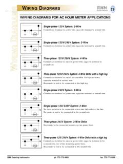
8 2. Service Application Manual SAM Chapter 620-37. Section 6A. TERMINAL MARKINGS AND INTERNAL WIRING diagrams single PHASE AND. polyphase MOTORS meeting NEMA standards . See Fig. 2-11 in which vector 1 is 120 degrees in advance of vector 2 and the phase sequence is 1, 2, 3. (See MG )*. MG Direction Of Rotation The standard direction of rotation for alternating generators is clockwise when facing the end of the machine opposite the drive.*. The direction of rotation of a generator mounted as a part of an engine-generator set is usually counterclockwise when facing the end opposite the drive.
9 The standard direction of rotation for all alternating-current single -phase motors, all synchronous motors, and all universal motors shall be counterclockwise when facing the end of the machine opposite the drive.*. MG Reversal Of Rotation, Polarity And Phase Sequence Alternating-current generators driven counterclockwise when facing the connection end of the coil windings will generate without change in connections, but the TERMINAL phase sequence will be 1, 3, 2.. Synchronous condensers and synchronous motors may be operated with counterclockwise shaft rotation viewed from the connection end of the coil windings by connecting them to leads in which the phase sequence is 1, 2, 3, in the following manner.
10 Power 1, 2, 3. Machine , 3, 2. ALTERNATING-CURRENT GENERATORS AND SYNCHRONOUS MOTORS. MG Connections And TERMINAL MARKINGS Alternating-Current Generators And Synchronous Motors One, Two, And Three Phase The alternating-current windings of three-phase alternating-current generators and synchronous motors shall have TERMINAL MARKINGS as given in MG for three-phase single -speed induction motors.*. The alternating-current windings of two-phase alternating-current generators and synchronous motors shall have TERMINAL MARKINGS as given in MG for two-phase single -speed induction motors.