Transcription of Test Bench - Operating Instructions - WABCO …
1 Test Bench - Operating Instructions2nd Edition815 000 217 38150002173 This publication is not subject to any update versions are available in INFORM Copyright WABCO 2004 Vehicle Control SystemsAn American Standard CompanyThe right of amendment is 002 000 217 3enTest BenchTable of Contents1 Safety Instructions12 Design and Function33 Operation in Connection with WABCO Test Instruction44 Erection45 Maintenance5 Annex6 Technical Data6 Accessories (Part of Delivery)6 Table of Contents435 197 000 0 Test Bench1/61 Safety InformationBefore erecting test Bench and testing sample,carefully peruse following safety specialist personnel with specific systemknowledge is authorized to testing starting any repair work, first read andunderstand all of this instruction sample on calibrated test Bench before starting any test that the shut-offcocks are having their correct normal position (seetest Instructions ).
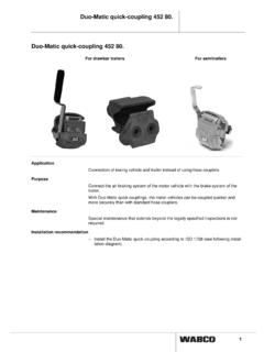
2 While performing sample test, absolutely keep topertinent test case of doubt about correct setting of sampleyou should consult vehicle manufacturer for theallowed dangersgrave personal injuries or deathImmediately impending dangersPersonal injury or material lossAdditional hints, info, tipsKeep to company's relevant accident preventionregulations and national to it that quick disconnects are safely pluggedon test Bench and test care to have test sample safely clamped loosen lock screws, hoses and equipmentparts then when the respective lines of the testbench are step Enumeration see preceding figure see following figure!WARNINGWARNINGCAUTION!CAUTIONS afety Bench2 Design and PurposeThe test Bench is designed for testing equipmentfrom compressed-air braking systems for StructureFig. 1 Test Bench Components1 Magnet test equipment2 Shut-off cocks with backend nozzles3 Test Bench ports4 Precision control valves5 Shut-off cocks with backend nozzles6 Insert7 Button actuator for draining8 Pressure reducing valve9 Drawers10 Central locking system11 Test Bench plate12 Vise (drawing shown offset)13 Circuit diagram14 Dash panel15 Pressure gauge16 NozzlesDesign and Bench3 FunctionFH = Precision Control Valve, High PressureFN = Precision Control Valve, Low Pressurefig.
3 2 Circuit Diagram High-pressure line runs to precision control valvesFH1 and FH2, via shut-off cocks 12 and 22, to testbench ports and as well as to pressuregages 1 and pressure-reducing valve D ( see Fig. 1, 8)for directing compressed air to low up to 10 bar shut-off cock may read set pressure from pressure gage line runs to precision control valvesFN1 and FN2, via shut-off cocks 11 and 21, to testbench ports and as well as to pressuregages 1 and Bench ports , , and run to iden-tical measuring units. The measuring units consistof one 1 liter air reservoir, one shut-off cock andone backend nozzle Squeezer TestsExclusively use test port for air squeezertests shut-off cock B for connecting both 20liter shut-off cock V for maintaining gener-ated pressure at desired 20 liter tanks are secured by safety test Bench port you may withdraw max10 bar of compressed air after opening shut-offcock Brake and Control EquipmentTest Bench is equipped with magnet test equipment( see Fig.)
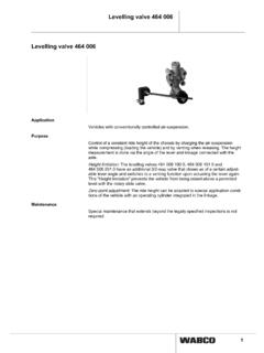
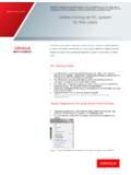
4 1, 1) for testing electropneumatic brakeand control equipment. It is suitable both for testingpulse magnets or permanent !123467!LFDesign and Bench3 Operation in Connection with WABCO Test InstructionYou will find the test instruction for the testsample under whenentering product number in product Bench 435 197 000 0 is adjusted for beingused for WABCO Test Instructions . Each TestInstruction itself contains information to be used onthe test Bench . This is followed by excerpts fromTest Instruction for truck brake valves 461 315 ..-Connect test sample to the numbered testbench ports. When doing so, heed terminalmarking on test 3 Connecting Test Sample to Numbered Test Bench Ports-Before starting the test, set shut-off cocks tonormal position according to 4 Shut-off Cocks Normal Position when testing Truck Brake Valves 461 315 ..-Further test sequence to be taken from ErectionHose fittings, vise and accessories to be foundin the test Bench erecting the test Bench , proceed as follows:-Connect dash panel to workbench plate usingthe enclosed hexagon head cap mounting holes are pre-drilled ( see , A).
5 Fig. 5 Work plate - Top ViewAMounting holes for dash panelBMounting holes for vise-Connect all connecting lines according to test Bench to house supply circuit ofcompressed working pressure: 22 barEach pressure gage has a red arresting screw onits housing underside. Its purpose is to protect themeasurement system from shipping arresting screw before tapped hole with the lock vise on workbench plate ( see Fig. 5, B)using the hexagon head cap screws mounting holes are pre-drilled( see Fig. 5, A).It is imperative to pre-connect water separator forprotecting test sample from contamination.!213411211222 Cock ABCDEF L V2346711122122onxxxoffxxxxxxx xxxxxxx!!!!CAUTIONO peration / Bench5/65 MaintenanceFrequency of maintenance work depends onhow often the test Bench is condensation Water from the 20 Liter Air Reservoirs-Press onto button actuator ( see Fig. 1, 7) foroperating both drain spindle and guide cheeks of vise as well asdrawer roller the SievesThe sieves are accommodated behind the out all caps F through 7 ( see Fig.)
6 1, 3)from distribution the Line FilterThe line filter prevents test Bench contaminationover the air supply line the Slide-In ModuleTurn off in-house network terminals for compressedair supply and the 9 fillister head screws on the rearside of the dash the fillister head all connecting lines between dashpanel and slide-in the connecting slide-in module lock ( see Fig. 6).Slide-in module lockfig. 6 Detail Test Bench - Back ViewCalibrating the Pressure GagesThe quality stickers on the pressure gagescontain date of next need to have calibration of the pressuregages carried out in compliance with yournational regulations.!CAUTION! BenchAnnexTechnical DataAccessories (Part of Delivery)Product number435 197 000 0 DimensionsHeightWidthDepth1,640 mm1,250 mm815 mmWeightApprox. 240 kgPermissible MediaMaximumOperating PressureAir22 barWork bench3 Drawers:ViseWidth of JawStroke100 mm85 mmPressure GaugeDiameterMeasuring RangePitchQuality Class forfine Measurements160 mm0 to 25 Test Equipment forSecondary 12 and 24 VDC /Maximum 1 A ACSupply230 VPieces Description1 Clamping Angle2 Hose ConnectorNW8/M ,000 long5 Hose ConnectorNW8/M ,500 long5 Screw Plug M Plug M Plug M with Counternut M Socket M Socket M Socket M Socket M Socket M Socket R 1/4" cone/M Ring for M Ring for M Ring for M Ring for M Ring for M for M for M for M for M for M Ring for M , inner1 Laminated HoseNW10/M ,200 longAnnex