Transcription of Testing and Evaluation of Grounding Systems: The Revision ...
1 IEEE Industry Applications Society Atlanta ChapterJanuary 19, 2010 Meeting1 Sakis MeliopoulosGeorgia Power Distinguished ProfessorSchool of Electrical and Computer Engineering,Georgia Institute of Technology,Atlanta, Georgia 30332-0250,Telephone: 404 894-2926, Fax: 404 894-4641 Email: or and Evaluation of Grounding Systems: The Revision of the IEEE Std 81 IEEE Industry Applications Society Atlanta ChapterJanuary 19, 2010 Meeting2 Purpose of GroundingLightning and Surge ProtectionStabilize Circuit Potential and Assist in Proper Operation of:- Communications- Relaying- Computers & Sensitive Electronic EquipmentLow Fault Circuit Path ImpedanceSafety, Safety, SafetyImprove Quality of Power ServiceGrounding and Bonding is Fundamental for a Safe and Reliable Power SystemIEEE Industry Applications Society Atlanta ChapterJanuary 19, 2010 Meeting3 Grounding , Bonding and Power Quality Recent studies indicate that as much as 80% of all failures of sensitive electronic equipment attributed to poor power quality may result from inadequate electrical Grounding or wiring on the customer s premises or from interactions with other loads within the premises.
2 Wiring and Grounding for Power QualityEPRI CU-2026, March 1990 However, many power quality problems that occur within customer facilities are related to wiring and Grounding practices. Up to 80% of all power quality problems reported by customers are related to wiring and Grounding problems within a facility. Power Quality Assessment ProcedureEPRI CU-7529, December 1991 IEEE Industry Applications Society Atlanta ChapterJanuary 19, 2010 Meeting4 Terms and DefinitionsOver the Years Grounding Design Procedures Have Been Developed as Well as Appropriate Standards, Most Notable: ANSI/IEEE Std 80-2000, IEEE Guide for Safety in AC Substation Grounding . IEEE Std 487-2007, Recommended Practice for the Protection of Wire-Line Communication Facilities Serving Electric Supply Locations. IEEE Std 998-1996, IEEE Guide for Direct Lightning Stroke Shielding of Substations.
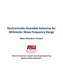
3 IEEE Std 1410-2004, IEEE Guide for Improving the Lightning performance of Electric Power Overhead Distribution Lines. IEEE Std 1243-1997, IEEE Guide for Improving the Lightning performance of Transmission Lines. National Electrical Code. National Electrical Safety Code. FIPS 94 and the Purpose of Verifying Designs, Testing Procedures have Been also Developed. Most Notable: ANSI/IEEE Std 81-1983, IEEE Guide for Measuring Earth Resistivity, Ground Impedance and Earth Surface Potentials of a Ground System. ANSI/IEEE Std , IEEE Guide for Measurement of Impedance and Safety Characteristics of Large, Extended or Interconnected Grounding Industry Applications Society Atlanta ChapterJanuary 19, 2010 Meeting5 The History of IEEE Std 80 IEEE Industry Applications Society Atlanta ChapterJanuary 19, 2010 Meeting6 The History of IEEE Std 80 IEEE Industry Applications Society Atlanta ChapterJanuary 19, 2010 Meeting7 Basis of Standards: IEEE 80 & IECNon-Fibrillating Body Current as a Function of Shock DurationIEEE Industry Applications Society Atlanta ChapterJanuary 19, 2010 Meeting8k50= (Non-Fibrillating, )k50= (Fibrillating, )k70= (Non-Fibrillating, )k70= (Fibrillating, )sbtIk=Value of Constant k for EffectiveRMS Values of IB.
4 Body Weight (kg)Fibrillating Current (mA RMS)0100200300010020406080 MaximumNon-FibrillatingCurrent ( )MinimumFibrillatingCurrent ( )DogssheepcalvespigsKiselev DogsFerris DogsIEEE Std 80, 1986 EditionIEEE Industry Applications Society Atlanta ChapterJanuary 19, 2010 Meeting9 Earth Current, Ground Potential Rise, Touch & Step 1. Determination of Soil Resistivities2. Computation of Ground Potential Rise3. Computation of Surface Voltages (touch and step)4. Safety AssessmentBasic Problems:secounterpoiearthneutralshieldf aultIIIII~~~~~+++=earthmatIRGPR~=IEEE Industry Applications Society Atlanta ChapterJanuary 19, 2010 Meeting10 Verification - MeasurementsKey Fact:Target Values Must be Determined in Design PhaseIEEE Industry Applications Society Atlanta ChapterJanuary 19, 2010 Meeting11 The History of the IEEE Std 81 First Edition:IEEE Std 81 1962 Revision :ANSI/IEEE Std 81-1983 IEEE Guide for Measuring Earth Resistivity, Ground Impedance, and Earth Surface Potentials of a Ground SystemTo Address Issues Related to Large Grounding Systems or Systems in Congested Areas:IEEE Std Guide for Measurement of Impedance and Safety Characteristics of Large, Extended or Interconnected Grounding SystemsAll of Above Standards were sponsored by.
5 Power System Instrumentation and Measurement CommitteeOf the IEEE Power Engineering SocietyIn the period 2003-2004, I served as the Chair of the Substations Committee of the IEEE Power Engineering Society. I initiated and succeeded in transferring sponsorship of the standard to the Substations Committee with the plan to combine the two standards into one single standard. The unified standard has been developed in committee (working group E6, Chaired by Dennis DeCosta) and we expect to ballot it within the next 12 months. IEEE Industry Applications Society Atlanta ChapterJanuary 19, 2010 Meeting12 ANSI/IEEE Std 81-1983 IEEE Guide for Measuring Earth Resistivity, Ground Impedance, and Earth Surface Potentials of a Ground System1. Purpose2. Scope3. Objectives of Tests4. Safety Precautions While Making Ground Tests 6. General Considerations of the Problems Related to Complexities Test Electrodes Stray Direct Currents Stray Alternating Currents Reactive Component of Impedance of a Large Grounding Coupling Between Test Leads Buried Metallic Objects 7.
6 Earth Resistivity8. Ground Methods of Measuring Ground Testing the Integrity of the Ground Instrumentation9. Earth Equipotential Potential Contour Step and Touch Voltages 10. Transient Impedance11. Model Tests12. Instrumentation13. Practical Aspects of MeasurementsAnnex A Nonuniform SoilsAnnex B Determination of an Earth ModelAnnex C Theory of the Fall of Potential MethodAnnex D BibliographyIEEE Industry Applications Society Atlanta ChapterJanuary 19, 2010 Meeting13 IEEE Std Guide for Measurement of Impedance and Safety Characteristics of Large, Extended or Interconnected Grounding Systems1. Purpose2. Scope3. References4. Safety Practices5. Factors Effecting Grounding System Measurements6. Preliminary Planning and Procedures7. Earth-Return Mutual Effects When Measuring Grounding -System Measurement Error Due to Earth Mutual Measurement Error Due to AC Mutual Mutual Coupling to Potential Lead From Extended Ground Conductors8.
7 Measurement of Low-Impedance Grounding Systems by Test-Current Signal Generator and Power Amplifier Portable Power-Generator Power System Low-Voltage Source9. Measurement of Low-Impedance Grounding Systems by Power System Staged Faults10. Current Distribution in Extended Grounding Test Analysis of Current Distribution in a Grounding Induced Current in the Angled Overhead Ground Current Distribution During a Staged Fault Test11. Transfer Impedances to Communication or Control Cables12. Step, Touch, and Voltage-Profile Measurements 13. Instrumentation Fast Fourier Transform Sine Wave Network Staged Low-Power Random noise Pulse Current Transformer (CT) Resistive Inductive Current Hall-Effect Probe14. Instrument performance Parameters 15. BibliographyIt was developed to address the special problems and issues associated with Testing large interconnected Grounding systems IEEE Industry Applications Society Atlanta ChapterJanuary 19, 2010 Meeting14 Present RevisionIEEE Std 81-XXXXG uide for Measuring Earth Resistivity, Ground Impedance, and Earth Surface Potentials of a Ground System1.
8 Scope2. References3. Definitions4. Test Objectives5. Safety Precautions While Making Ground Station Ground Special Considerations6. General Considerations on the Problems Related to Measurement7. Earth Methods of Measuring Earth Interpretation of Guidance on performing field measurements8. Ground Impedance9. Testing Local Potential Differences10. Integrity of Grounding Systems11. Current Splits12. Transient Impedance of Grounding System13. OtherANNEX A (INFORMATIVE) SURFACE MATERIAL RESISTIVITYANNEX B - Megohm Clamp-On Ground Smart Ground Transient Impedance MeterIEEE Industry Applications Society Atlanta ChapterJanuary 19, 2010 Meeting15 Grounding System Measurements Ground Impedance Measurement MethodsThe 2-Point MethodThe 3-Point MethodThe Fall of Potential MethodThe 62% RuleThe Ratio MethodThe Tag Slope MethodThe Intersecting Curve MethodStaged Fault TestsDriving Point ImpedanceThe SGM Method Continuity/Integrity Testing Soil Resistivity Measurements Touch and Step Voltages Other Tests (Tower/Pole Ground, Transfer V.)
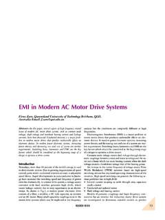
9 IEEE Industry Applications Society Atlanta ChapterJanuary 19, 2010 Meeting16 RaaaaRaa 221422224 + ++=llIVR= 12haaaVoltMeterSourceCurrentMeterEarth SurfacelFour Point Wenner MethodIEEE Industry Applications Society Atlanta ChapterJanuary 19, 2010 Meeting17 Limitations of the Wenner MethodaIjxaIrRIVeem =ajxaraIVeem = 2 Example: Soil of 10 , separation 300 feet, measurements at 150 Hz. Compute error 12haaaVoltMeterSourceCurrentMeterEarth SurfacelIEEE Industry Applications Society Atlanta ChapterJanuary 19, 2010 Meeting18 Basic PrinciplesBasic ArrangementIVRg=IEEE Industry Applications Society Atlanta ChapterJanuary 19, 2010 Meeting19 The Fall of Potential MethodThe 62% RuleIEEE Industry Applications Society Atlanta ChapterJanuary 19, 2010 Meeting20 Optimal Voltage Probe Location The 62% Rule =rDrIVp112 + = =rDrDaIVVRpaa11112 =DaIVa112 IEEE Industry Applications Society Atlanta ChapterJanuary 19, 2010 Meeting21 Optimal Voltage Probe Location The 62% =Dr0111= +rDrD + = =rDrDaIVVRpaa11112 CompareaIVRag 2==Ra= Rgrequires that:Solving for r/D yields.
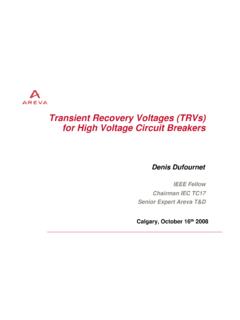
10 IEEE Industry Applications Society Atlanta ChapterJanuary 19, 2010 Meeting22 The Fall of Potential Method 62% Rule and Two Layer Soil D x h 1 21212 + =KIEEE Industry Applications Society Atlanta ChapterJanuary 19, 2010 Meeting23 Ground Impedance MeasurementsThe Fall of Potential Method Measurement ProcessTHEORYFlat Curve PortionCurrentReturnElectrodeCurrent SourceVoltmeterVoltageProbeApparent ResistanceGroundUnderTestTrue Ground ResistanceDistance from Ground Under TestIEEE Industry Applications Society Atlanta ChapterJanuary 19, 2010 (feet)Resistance (Ohms)The Fall of Potential MethodEarth Voltage Distribution - Actual MeasurementsContributor: American Electric Power276 x 276 ft2160 ftCurrentElectrodeVoltmeterIR = V / IIEEE Industry Applications Society Atlanta ChapterJanuary 19, 2010 Meeting25 Factors Affecting Ground Impedance Measurement Difficulty reaching true remote earth reference voltage Effect of Auxiliary Electrode Location (Earth Current Return) Size and location of voltage probes Interaction Between Instrumentation Wires Interference from Overhead Lines and their Grounding Background 60 Hz Voltage and Harmonics Ground Impedance MagnitudeThe Fall of Potential MethodIEEE Industry Applications Society Atlanta ChapterJanuary 19, 2010 Meeting26 Fall of Potential Method ErrorsInteraction between Instrumentation Wires =dDlMeln20 fDe 2160=(d,De in feet)whereCurrentReturnElectrodeVoltageP robeGround SystemUnder TestMCurrent Source I( )