Transcription of Testing Corrosion Protection Systems - Fluke …
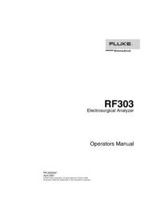
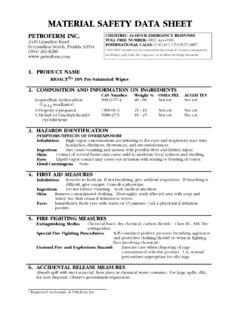
1 ReferenceElectrodeBonding BusZincApplication NoteTesting CorrosionProtection SystemsIntroductionThe Corrosion Protection system onyour boat should be checked atregular intervals. Failure to do so canlead to costly and time consumingrepairs. The tools you ll need for thejob include a high quality digitalmultimeter and a reference elec-trode. Fluke multimeters are ideal forcorrosion system Testing for severalreasons. They are accurate, rugged,reliable, and most important, theyhave 10 Megohm input impedancein the DC volts function. The highinput impedance will allow you totest your boat in either fresh wateror salt water with repeatable application note will helpyou understand some basic corrosionmechanisms and the methods usedby professionals to test corrosionprotection Systems . At the end of theapplication note, you ll find a list ofreferences for further reading on Corrosion mechanismsIn general, the term Corrosion refers to the unwanted loss of metalfrom the hull and/or under-watermetal fittings of the vessel.
2 Thereare two main types of Corrosion mechanical and electrical. Under theelectrical category, there are threecommon subcategories: galvaniccorrosion, stray current Corrosion ,and crevice Corrosion occurs whentwo dissimilar metals are connectedtogether electrically in the presenceof a conductive electrolyte. Atoms inthe less noble metal give up theirelectrons to the more noble metaland are released to flow (corrode)into the electrolyte in the form ofpositively charged current Corrosion occurswhen a foreign voltage source pullselectrons out of the metal allowingthe ions to flow as Corrosion is actually aform of galvanic Corrosion butinvolves only one metal. A portion ofthe metal (in the crevice) becomesactive (less noble) due to loss ofoxygen while the remainder stayspassive. If electrolyte is present, agalvanic couple is formed and theactive metal is converted to ions andenters the electrolyte of galvaniccorrosionMaterials used in the construction ofmarine vessels are chosen usingvarious criteria including cost,mechanical strength, workabilityand Corrosion resistance.
3 When wewant to compare metals according totheir Corrosion resistance, we referto a ranking list called the GalvanicSeries of Metals often referred to asthe noble scale . This scale indi-cates the relative affinity that eachmetal has for its electrons, , itranks the metals according to theirelectron bonding at the active (less noble)end of the scale will give up theirelectrons and corrode more easilythan metals on the passive (morenoble) end of the Series of Metals(alloys may vary according to composition)Active (least noble)MagnesiumIronLeadZincBrassTitanium AluminumTinSilverCadmiumCopperPlatinumSt eelBronzePassive (most noble)GoldUnderwater metals can be pro-tected if they are supplied with extraelectrons. Active metals like zinc arecommonly used to protect morenoble metals. If the two metals areimmersed in the same electrolyteand deliberately connected by anelectrical bonding system , the zincwill give up its electrons to protectthe more noble metal.
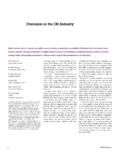
4 In this con-figuration the zinc is called an anodeand the protected metal is called !1000V MAXmAACOM!!MIN/MAXRANGEHOLD HRELmA/AAmVVOFFRESETMIN MAXOFFmA/AmVVA10A MAX320 mA MAXA0 102030kMIN3027 MULTIMETER26 TRUE RMS MULTIMETERRANGEHOLD1000 VCAT600 VCATFUSEDV40mA10 ACOM40 CALVOFFHzVAmV40V 1kHzHz 20kHz73 MULTIMETER0102030 VACOFFAAVV300mVAUTORANGE MANUAL RANGEPRESS300mA10 AFUSEDTOUCH HOLD600 VCATVCOMT esting with areference electrodeWhen a metal is in contact with anelectrolyte such as sea water, themetal will establish a natural poten-tial or voltage with respect to theelectrolyte. This natural potential (or freely existing potential) is thevalue that exists when no extraelectrons are being supplied or re-moved by an outside voltage can measure this potential witha digital multimeter and a referenceelectrode.
5 The reference electrodeallows us to make an electrical con-nection to the sea water with aknown, repeatable value, , areference electrodes are oftencalled half cells because theycontain a metal and a metal com-pound. Popular types are Copper-Copper Sulfate and Silver-SilverChloride. Marine system tests areoften conducted with a Silver-SilverChloride electrode (see descriptionin reference 1).The principle of the test isstraightforward: We want to estab-lish that the Corrosion protectionsystem is supplying enough elec-trons to raise the potential of theprotected metal 250 mV (1/4 Volt)above the freely existing value. Thetest procedure is as follows: (Refer todrawing on page 1).1. Set the multimeter function toDC Connect the reference electrodeto the volts input jack and placethe electrode in the water. Bestresults are obtained when theelectrode is located away fromthe Connect the multimeter commonjack to a probe that will be usedto contact each piece of under-water Touch the common probe to eachunderwater metal fitting andrecord the millivolt value as dis-played on the meter.
6 If all under-water metal fittings are con-nected together with a bonding system as shown on page 1, thenall readings should be typical values for severalmetals are listed in Table *OverUnpro-Protected*tected* * Voltages given in this table are typical valuesobtained using a silver/silver-chloride refer-ence electrode. Values may vary according toalloy and type of can cause paint topeel from a metal hull, or chemicaldamage to a wooden hull. Refer toreferences 1 & 2 for more informationon the dangers of over Protection anddetails about bonding for additionalinformation1. Boat and Yacht Corrosion Control;by Yacht Corrosion Consultants2970 Seaborg AvenueVentura, CA 930032. Boatowner s Illustrated Handbookof Wiring; by Charlie WingInternational MarineCamden Marine3. Your Boat s Electrical system ;by C. Miller and MaloneyHearst Marine BooksFluke CorporationPO Box 9090, Everett, WA USA 98206 Fluke Europe Box 1186, 5602 BDEindhoven, The NetherlandsFor more information (800) 443-5853 orFax (425) 356-5116 Europe/M-East (31 40) 2 678 200 orFax (31 40) 2 678 222 Canada (905) 890-7600 orFax (905) 890-6866 Other countries (425) 356-5500 orFax (425) 356-5116 Web access: 1998 Fluke Corporation.
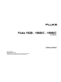
7 All rights in 11/98 B0269UE N Rev BPrinted on recycled Multimeters for Marine ApplicationsThe following Fluke Digital Multimeters arerecommended for use in marine 36 ClampMeter True-rmsresponding AC current to 600A DC current to 1000A AC and DC voltageto 600 Volts Max Hold Continuity beeperFluke 27 Fully sealed,waterproof case Touch Hold captures stablereadings Volts, ohms, amps,continuity, diodetest Current with rangesfrom 320 A to 10 AFluke 26 Series IIISame features asFluke 73 Series III,plus: Rugged, overmoldedcase Tough, electrical testlead set withsilicone insulationand alligator clip True-rms ac voltage AC/DC current withranges from mAto 10A Lo OhmsFluke 73 Series III Touch Hold captures stablereadings Auto and manualranging Holster with Flex-Stand included Volts ac and dc Resistance Diode test/continuity beeper AC/DC current withranges from 32 mAto 10 AFluke 12 BPut basic testson automatic VCheck auto-maticallyswitches frommeasuring ohms/continuity to acor dc volts Capacitance, to10k microfarads Continuitycapture locatesintermittentopens and shorts Min/Max record-ing with relativetime stampOther marine application notes available from Fluke .
8 Troubleshooting Marine Engine Electrical Systems Troubleshooting Outboard Motor Magneto your worldup and 600A 1000 ACLAMP METER36 COMV600 VTRUE RMSDC / ACZEROADC