Transcription of Testing Electrical Systems with a Digital Multimeter
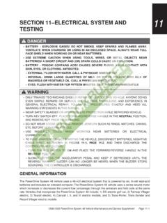
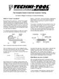
1 Testing Electrical Systems with a Digital Multimeter Perhaps the most important tool you'll use in troubleshooting auto Electrical Systems is the Multimeter . Basic multimeters measures voltage, current and resistance, while more elaborate multimeters, such as the Fluke 78, or Fluke 88 have featues that can check things such as frequency, duty cycle, dwell, make diode tests, and even measure temperature, pressure and vacuum. Starter Current Starting system troubles are often confused with charging system problems. Many a dead battery has been replaced when the real cause was a faulty charging system. Be sure that the charging system is functioning properly before you replace the battery. Make sure the battery is charged and passes a load test, then look for resistance in the starter circuit if the engine still cranks slowly.
2 Investigate excessive current draw; check for worn-through insulation, a seized or tight engine, a faulty starter, etc. If the starter turns the engine slowly, the current draw is not high, and the battery is in good condition, check the resistance in the starter circuit. Fig 6 - Measuring Starter Current Draw Determine how much current the starter is drawing by using Fluke's 80i-401, 80i-1010, or 90i-610s Inductive Current Clamp on the starter cable. This accessory will allow the Multimeter to measure starter current up to 1000 amps. Check manufacturer's specs for exact figures. Alternator AC Leakage An alternator generates current and voltage by the principles of electromagnetic induction. Accessories connected to the vehicles charging system require a steady supply of direct current at a relatively steady voltage level.
3 You can't charge a battery with alternating current, so it must be rectified to direct current.. Fig 4 - Checking Ripple Voltage Ripple voltage or (AC voltage) can be measured by switching your DMM to AC and connecting the black lead to a good ground and the red lead to the "BAT" terminal on the back of the alternator, (not at the battery). A good alternator should measure less than .5 VAC with the engine running. A higher reading indicates damaged alternator diodes.. Fig 5 - Alternator Leakage Current To check alternator diode leakage, connect the Multimeter in series with the alternator output terminal when the car is not running. Leakage current should be a couple of milliamps at most; more often, it will be on the order of milliamps. Use care when disconnecting the alternator output wire; make sure the battery is disconnected first.
4 Alternators A DMM's accuracy and Digital display make regulator/alternator diagnosing and adjusting easy. First determine if the system has an integral (internal) regulator, then whether it's type A or B. Type-A has one brush connected to battery + and the other brush grounded through the regulator. Type-B has one brush directly groundedand the other connected to the regulator. Next, isolate the problem to alternator or regulator by bypassing the regulator (full-fielding). Ground Type-A field terminal. Connect Type-B field terminal to Battery +. Ifthe system now charges, the regulator is faulty. Use a rheostat if possible. Otherwise, just idle the engine (lights on) so the voltage doesn't exceed 15V. Fig 2 - Verifying a Good Alternator The battery must be fully charged (see fig.)
5 1). Run the engine and verify that no-load voltage is - (check as in fig. 1). Next, load the alternator to rated output current with a carbon pile across the battery. Run the engine @ 2000 RPM. Check the current with an 80i-410 or 80i-1010 current clamp. The unit must maintain at least @ rated output. Fig 3 - Checking Field Current Worn brushes limit field current, causing low alternator output. To test: load unit as in Figure 2 and measure field current with current clamp or use 10A jack on DMM. Readings range from 3 to 7 amps. On integral GM units: with alternator not turning, jump terminals #1 & #2 (fig. 4) together and connect both to Batt + with DMM in series set to measure 10 amps. Field current should be between 2 & 5 amps, higher current with lower battery voltage.
6 Control battery voltage by loading it with a carbon pile. Batteries Charging system problems often come to you as a "no-start" complaint. The batterywill have discharged and the starter won't crank the engine. The first step is to test the battery and charge it if necessary (fig 1). No-Load Test Voltage Percent Charge to 100% 75% 50% 25% Readings obtained at 80 F (27 C) Fig 1 - Measuring System Voltage Bleed the surface charge from the battery by turning on the headlights for a minute. Measure the voltage across the battery terminals with the lights off (see chart). When possible, individual cell specific gravity should be checked with a hydrometer. A load test should be done to indicate battery performance under load.
7 Voltage tests Feedback Carburetor Using the Fluke 78's built-in dwell meter to measure M/C dwell can tell you whether it's a fixed or varying cycle: Fixed dwell occurs in several instances: 1) when the engine is in open loop (cold engine) 2) the engine is under wide-open throttle (hot engine) 3) the oxygen sensor has cooled off, due to prolonged idling, and re-entered open loop (hot engine). Varying dwell tells you the engine is in closed loop. It also indicates whether the carburetor is supplying a rich or lean mixture. Fig 9 - Measuring Dwell on a Feedback Carburetor The longer the solenoid's "on-time," the higher the dwell -and the leaner the fuel mixture delivered by the carburetor. The shorter the "on-time," the lower the dwell -and the richer the fuel mixture.
8 A normally operating system will have a varying dwell, but it should average about 30%. Circuit Resistance Ohm's law (E=IxR) tells us that even very low resistance in the starter circuit will cause the starter to turn slowly, because of low voltage. For example: in a system drawing 200 amps, ohms resistance in the starter cable will cause a 2 volt drop in voltage at the starter; ohms is too little for all but the most expensive and sophisticated ohmmeters to measure, but measurements of voltage drop will indicatewhere there is resistance. Voltage Drop In automotive circuits even the smallest loss of voltage will cause poor performance. Set your Fluke Multimeter in the mV or VDC setting and connect the meter + lead to the side of the device nearer the battery + terminal and the - lead tothe side nearer the battery - terminal or ground and engage the Min/Max function.
9 Current must be flowing for the meter to register the voltage drop found. This procedure is helpful on components and connections (both on the + feed side and - ground side) except solenoids, which read battery voltage if you measure across them when the engine is being cranked. Voltage drops should not exceed the following: 200 mV Wire or cable 300 mV Switch 100 mV Ground 0 mV to <50 mV Sensor Connections Connections Click on graphic to view larger image. Fig 7 - Testing for Excessive Voltage Drop Determine if there is resistance in the circuit by measuring the voltage drop across each connection and component in the starter circuit while cranking the engine. Measure the voltage drop between the battery post and the connecting cable, the solenoid posts and the wires that attach to them, and across the solenoid itself.
10 Also check the connection on the starter, alternator (feed and ground side) and the ground strap connection to the engine block and body. Condensers Fluke analog/ Digital multimeters can also be used for checking automotive capacitors (condensers). The movement of the bar graph will show that the DMM is charging the condenser. You'll see the resistance increase from 0 to infinity. Be sure the switch the leads and check both ways. Also make sure to check condensers, both hot and cold. Fig 13 - Checking Condenser Leakage Check for leaking condensers with the Ohms function. As the condenser charges up, the resistance should increase to infinity. Any other reading indicates that you should replace the condenser. If the condenser is on the car, make Cooling Systems / Temperature Measurement The Fluke 78's built-in temperature function makes it quick and easy to check engine cooling Systems for proper temperature, which is critical with today's computer-controlled engines.