Transcription of The Electrostatic Semiconductor Wafer Clamping/Chucking ...
1 The Electrostatic Semiconductor Wafer Clamping/Chucking System (ESC) The Electrostatic chuck (ESC) is used in a variety of Semiconductor processes to hold the Wafer during processing. ESCs employ a platen with integral electrodes which are biased with high voltage to establish an Electrostatic holding force between the platen and Wafer , thereby chucking the Wafer . Presently, most process tool manufactures use low speed DC signalsto control high voltage power supplies. This allows them to control the voltage set-points and sequencing of the clamp and de-clamp functions of the ESC.
2 While this provides basic ESC operation, the technique limits the complexity of the bias signals that can be applied to the ESC. In order to provide greater waveform sophistication, Trek has incorporated a microprocessor-controlled arbitrary waveform generator in combination with a high speed, high voltage amplifier and Electrostatic Voltmeter so that a wide range of clamp sequences may be generated and monitored in order to optimize performance of the clamping and de- clamping process by controlling the ramp.
3 Overshoot and duration of the HV signal Several process tool companies have begun to use Trek HV amplifiers in conjunction their own signal generators to produce more advanced ESC waveforms to drive their platens. Building upon this technique, Trek has advanced the technology further by offering a complete solution for generation, high voltage and Wafer monitoring, all in a single instrument. This makes it easy to produce waveforms which have tailored risetime, controlled overshoot, adjustable bias and sophisticated trailing edge shape.
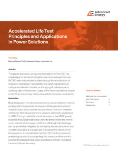
4 This system allows optimization of the Electrostatic force profile needed to provide effective ESC operation for each Wafer /platen application. As effective ESC operation must address issues of minimum clamping time, variation in clamping force during the Wafer processing, as well as Wafer charging control to minimize Wafer sticking to the platen, etc. Figure 1. Trek 640 Electrostatic Chuck Optimizer Figure 2. Trek 645 Production Electrostatic Chuck Driver Advanced Energy's marriageof high voltage amplifier technology and arbitrary waveform generation provides the Semiconductor tool manufacturer with a new way to control the Electrostatic chuck with better clamping , more efficient de-clamp and minimum residual Wafer charge.
5 Advanced Energy provides adevelopment system and a production driver in an easy to use configuration with numerous features available for the first time. APPLICATION NOTEMany end users regard the design of an Electrostatic chuck as a black art. End users blame process errors on the design implementation of the ESC so having the flexibility to create diverse waveforms will be a strategic advantage to the process tool manufacturer. Also, as line widths shrink below the present 45 nm state of the art, damage in processing due to Electrostatic discharge (ESD) becomes a serious issue.
6 Again, the ability to tailor the shape of the falling edge of the ESC waveforms minimizes the possibility of ESD and makes the product more attractive for next generation processing. ESC Optimization and Control A new approach to allow for optimization and control of the ESC voltage waveform/profile at the system designer/user level is provided by Trek through the introduction of a new method and product family. The new family utilizes Arbitrary HV Waveform Generation technology and provides both a development system called an ESC Optimizer (Trek 640) and a production Chuck Driver (Trek 645) having the required functionality as developed through use of the 640 Optimizer by the ESC system designer/user for a particular platen and process.
7 The Optimizer provides hardware and software to allow the ESC system tool manufacturer to quickly and easily develop and evaluate the clamping performance achieved using his own custom waveforms. The production driver instrument is a compact device that accepts a download of the optimized high voltage waveforms program and helps to bring a new tool online quickly and easily with no surprises in the performance of the Electrostatic chuck. The two products are shown in Figures 1 and 2. They are discussed in detail below.
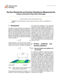
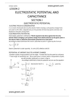
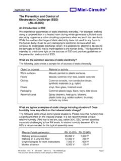
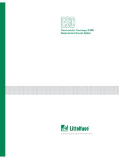
8 Arbitrary HV Waveform Technology The Trek models 640 and 645 both utilize arbitrary waveform generator (AWG) technology using easy-to-use software to allow various waveforms to be created and evaluated by the user. When the AWG is coupled to a HV amplifier, an ESC driver with unprecedented performance results. MemoryClockDACDACHV AmpHV AmpFigure 3. The arbitrary waveform generator and the high voltage amplifier working together Figure 4. A pair of waveforms useful for ESC applications. The Trek ESC software and hardware allows the user to easily create waveform files with Excel or by using Trek s waveform generation software.
9 The resultant waveform files are converted to analog signals and amplified by Trek HV amplifiers in the ESC driver instrument. See Figure 3. Virtually any waveforms are possible. To illustrate the utility of this technology, a very useful waveform for the application is shown in Figure 4. The waveform in Figure 4 has intentional overshoot to pull the Wafer in firmly and an oscillatory tail intended to minimize any residual charge that might otherwise remain on the Wafer after the process is complete.
10 Note that an ESC 2 circuit using simple high voltage supplies could not produce waveforms like those in Figure 4. Advanced Software Optimization of the ESC performance involves evaluating a variety of waveforms by the design engineer. The Trek 640 and 645 both offer easy-to-use software allowing the user to build waveforms quickly and easily. This is done by creating them using Excel or by drawing them using a mouse. As shown in Figure 5, the software for the Trek 640 breaks the ESC waveform into three segments called Clamp, Process and De-Clamp.