Transcription of Surface Resistivity and Surface Resistance Measurements
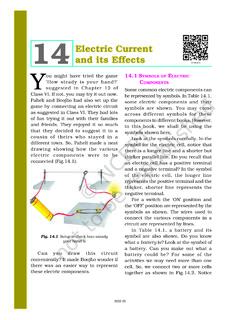
1 Surface Resistivity and Surface Resistance MeasurementsUsing a Concentric Ring Probe TechniqueWilliam A. Maryniak, Toshio Uehara, Maciej A. NorasAbstractThe relationship between Surface Resistivity and Surface Resistance is established IntroductionConcepts of Surface Resistance and Surface resis-tivity can be sometimes confusing. Definitions ofboth terms can be found in many books and stan-dards [1 4]. Surface Resistance ,Rs, is defined inall of the aforementioned literature sources as theratio of a DC voltageUto the current ,Isflowingbetween two electrodes of specified configurationthat are in contact with the same side of a materialunder test (Figure 1).Rs=UIs(1) Surface Resistivity s, on the other hand, is deter-mined by the ratio of DC voltageUdrop per unitlengthLto the Surface currentIsper unit widthD. s=ULIsD(2)LDUelectrodesmaterialFigure 1: Basic setup for Surface Resistance andsurface Resistivity Resistivity is a property of a material.
2 The-oretically it should remain constant regardless ofthe method and configuration of the electrodesused for the Surface Resistivity measurement. Aresult of the Surface Resistance measurement de-pends on both the material and the geometry ofthe electrodes used in the measurement. Thephysical unit of Surface Resistivity is Ohm ( ). Thelegitimate unit of the Surface Resistance is alsoOhm. Because of that Surface Resistivity and thesurface Resistance are often mixed up. In orderto differentiate between the two, Surface resistiv-ity is often expressed also in Ohm/square ( /sq.)which is nota valid unit from the dimensional anal-ysis point of Surface Resistivity andsurface current density and Surface cur-rent densityIt is possible to establish a relationship betweenthe Surface Resistance and Surface Resistivity forany electrode configuration. An idea of the cur-rent density is very helpful in understanding of thatrelationship.
3 Consider two samples of a materialas shown in Figure 2. With a constant voltageUand both samples made of the same material theamount of current flowing through the material willbe different. The thicker bar (sample #1) conducts"more easily" than the thin bar (sample #2). Onemay use a water pipe analogy - given a constantwater pressure, there will be more water per unittime coming through the pipe with a larger diame-ter. The flow density, be it water or electric current ,is the amount of flow passing through a unit areaof the pipe or the sample of the material. The sur-face area is perpendicular to the direction of theflowing current (or water).APPLICATION NOTES urface Resistivity and Surface Resistance MeasurementsUsing a Concentric Ring Probe TechniqueLDUelectrodesmaterialD(a) Sample # (b) Sample # 2: current the voltageUis kept constant, the currentdensity for the thin and the thick bar is the electric current density is often expressed by:J=ISwhereIis the current andSis the Surface area,and is measured in [A/m2].
4 Surface current den-sity is the next concept helpful in understandingthe relationship between the Surface resistanceand Surface Resistivity . Consider Figure 1, whereboth electrodes are on the same side of the mate-rial. It is assumed that electric current flows on thesurface of the material only. In reality, this is notexactly true. There is always a portion of that cur-rent flowing through the bulk of the material. How-ever, in order to make it possible to compare sur-face properties of various materials, it had beenpresumed that the Surface current flows throughinfinitesimally thin Surface layer. This layer is sothin, that the thickness of it can be neglected. Sur-face current densityJsis therefore defined as:Js=ID,where D is a width of the Concentric ring electrodes con-figurationThe relationship between Surface Resistivity andthe Surface Resistance for a concentric ring probegeometry can be found by defining a Surface cur-rent density in the area between rings.
5 Knowingthe Surface current density, it is possible to find anelectric field intensity between the electrode rings(Figure 3).R2R1 Figure 3: Surface Resistance and Surface resistiv-ity measurement configuration for concentric : R1outer radius of the center electrode, R2inner radius of the outer ring electrode,as it is shown in Figure 3 (see also Figure 5). Thesurface current densityJsfor a concentric ringsconfiguration is determined as:Js=Is2 r,(3)2 Resistivity and Surface Resistance MeasurementsUsinga Concentric Ring Probe Techniquewhere the radiusrvaries fromR1toR2. It isimportant to remember that when testing the sur-face Resistivity (or Resistance ) of any material, it isassumed that all the currents flow between elec-trodes along the Surface and do not penetrate intothe bulk of the material. In order to ensure thatthe Surface currents are measured properly, somemore advanced techniques for Surface resistivitymeasurements have been developed [1, 2, 4].
6 TheOhm s law describes relationship between a cur-rent density J and an electric field intensityE. It isalso valid for the Surface currents:Js=E s,(4)Therefore, it is possible to find electric field be-tween the concentric rings by solving the followingdependency (using equation 3 and 4):E= sIs2 r,(5)The voltage between electrodes can be found byintegrating the electric fieldEfromR1toR2:UR1,R2= R2R1E dr== R2R1 sIs2 rdr= sIs2 R2R11rdr= sIs2 ln(R2R1)(6)SubstitutingRs=UIs:Rs= s2 ln(R2R1)(7)After rearrangements, the Surface Resistivity is re-lated to the Surface Resistance by a constant thatdepends on the geometry of the electrodes only: s=Rs2 ln(R2R1)=Rs k(8)Wherekis frequently called a geometry 4: Surface Resistivity measurement 5: Concentric ring 4 presents a typical Surface Resistivity mea-surement setup using a Resistivity meter and aconcentric ring probe (Figure 5). The resistiv-ity meter is capable of measuring Surface resis-tivities directly, utilizing various configuration 3 Surface Resistivity and Surface Resistance MeasurementsUsinga Concentric Ring Probe Techniqueelectrodes.
7 Meter provides a constant voltageUand measures the currentIflowing between elec-trodes. ResistanceRsis then easily calculatedand the value of Resistivity is equal to the value ofresistance multiplied by the geometry electrodes are especially constructed tosimplify calculations of Surface Resistivity and thegeometry coefficient is equal to a simple of industrial standards use this simplified ap-proach [1, 2, 4].Example 1:Consider the following measurementconfiguration:R1= [mm],R2= [mm],U= 10 [V].The current measured during the test was equaltoIs= 1 10-6[A]. The Surface Resistivity of the ma-terial under test can be calculated from the equa-tion 8: s=Rs2 ln(R2R1)==UIs2 ln(R2R1)==10 [V]10-6[A]2 ln( [mm] [mm])== 107[ ] 2 ln( )== 107[ ] 10 == 108[ ]3 Additional remarksWhile conducting the Surface Resistivity and thesurface Resistance tests, it is important to considersome additional components affecting the test re-sults.
8 The electric Resistivity of any dielectric ma-terial depends on many environmental factors. Itcan change with humidity, temperature, etc. Forthis reason it is recommended to condition the testsample before the measurement. Another impor-tant aspect is to ensure a proper contact betweenelectrodes and the tested material. Electrode sys-tems can be made of various materials and maycome in various shapes and configurations. Theway of electrode contacts the material under testhas a very significant influence on the result ofa measurement. The DC voltage level used fortesting is also an important issue. Usually resis-tivity of the material depends on the value of theapplied voltage and the time span during whichthe sample was energized. All these contributingfactors and criteria are described in appropriateguides and standards [1 4].References[1] ASTM Standard D testmethods for D-C Resistance or conductance ofinsulating materials, 1999.
9 [2] ESD STM measurement of static dissipativeplanar materials, 2001.[3] Michael B. Measurement, Instru-mentation and Sensors Handbook, chapterElectrical Conductivity and Resistivity . CRCP ress, 1999.[4] IEC 61340-5-1 Standard. Electrostatics - part5-1: Protection of electronic devices fromelectrostatic phenomena - general require-ments, international contact information, visit 970 221 0108 Specifications are subject to change without notice. Not responsible for errors or omissions. 2020 Advanced Energy Industries, Inc. All rights reserved. Advanced Energy and AE are trademarks of Advanced Energy Industries, Inc.