Transcription of Experiment 15: Ohm’s Law
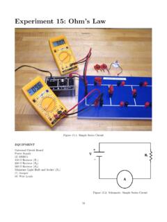
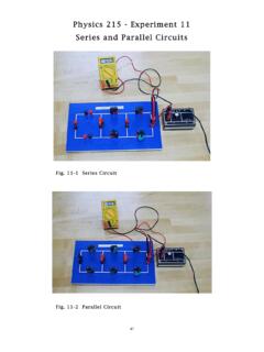
1 Experiment 15: Ohm s LawFigure : Simple Series CircuitEQUIPMENTU niversal Circuit BoardPower Supply(2) DMM s150 Resistor (R1)330 Resistor (R2)560 Resistor (R3)Miniature Light Bulb and Socket (R4)(1) Jumper(6) Wire LeadsFigure : Schematic: Simple Series Circuit7980 Experiment 15: Ohm s LawAdvance ReadingText:Ohm s Law, voltage, resistance, Manual: Appendix B,Appendix C-DMMO bjectiveThe objective of this lab is to determine the resistanceof several resistors by applying Ohm s Law. Studentswill also be introduced to the resistor color code andrefresh their graphing s Law states that the current,I, that flows in acircuit is directly proportional to the voltage,V, acrossthe circuit and inversely proportional to the resistance,R, of the circuit:I=VR( )In this Experiment , the current flowing through a resis-tor will be measured as the voltage across the resistoris varied. From the graph of this data, the resistance isdetermined for Ohmic resistors (Ri,i= 1, 2, 3). Non-Ohmic resistors (R4, light bulb) do not obey Ohm are connected in seriesso that thecur-rent flows throughthem.
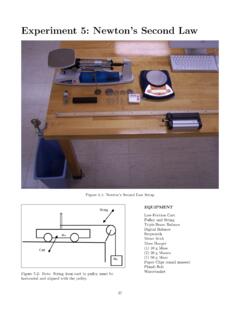
2 The ideal ammeter has a re-sistance of zero so that it has no e ect on the ammeters have some internal are connected in parallelto resistiveelements in the circuit so that they measure thepoten-tial di erence across(on each side of) the ideal voltmeter has infinite internal voltmeters have approximately 10 M (10 106 )internal resistance so that only a minuscule amount ofcurrent can flow through the voltmeter. This keeps thevoltmeter from becoming a significant path for currentaround the element being are labeled with color-coded bands that indi-cate resistance and tolerance. The first two color bandsgive the first two digits of the value (Fig. ). Thethird band gives the multiplier for the first two, in pow-ers of 10. The last band is the tolerance (Fig. ),meaning the true value should be x% of the colorcode value. Refer to Table for standard color is no need to memorize the color codes for example, a resistor that has two red bands and ablack multiplier band has a resistance of 22.
3 Figure : Color Code SchematicColorNumberMultiplierBlack0100 Brown1101 Red2102 Orange3103 Yellow4104 Green5105 Blue6106 Violet7107 Grey8108 White9109 ToleranceGold5%Silver10%(No Band)20%Table : Resistor Color Code ValuesPrelab 15: Ohm s Law81 Name:1. Write the equation and a qualitative statement for Ohm s Law. (20 pts)2. What are ohmic and non-ohmic devices? (20 pts)3. Complete the following statement: An ideal ammeter has an internal resistance of, while anideal voltmeter has an internal resistance of. Explain why these are desirable attributes forthe respective measuring instruments. (20 pts)4. plotted, what value is obtained from the slope?Notethat we are investigating the functionI=V /Rand fitting our data to the slope-intercept equation of a line. (40 pts)82 Experiment 15: Ohm s LawPROCEDUREPART 1: Measures of Resistance1. Determine the nominal resistance for the three re-sistors: interpret the color codes according to thecolor code chart in Table Measure the actual resistance,R, of the three re-sistors using the ohmmeter and record them in thetable An ideal ammeter has no resistance; this ammeterdoes have a small resistance.
4 Measure the resistanceof the ammeter (200 mA DCA).PART 2: Ohm s Law Applied4. Build a simple series circuit usingR1, an ohmmeter,an ammeter, and a jumper (This will look similarto Fig. , but without the power supply).5. Measure the equivalent resistance of the circuit us-ing the ohmmeter and record this value in the tableprovided. Include units and Remove the ohmmeter and connect the unpluggedpower supply to the circuit. Connect a voltmeter tothe circuit, across the power supply leads (in paral-lel).7. Have your TA check your circuit. Plug in the powersupply and turn it Test Ohm s Law (V=IR) by verifying that thecurrent increases linearly with applied voltage. Ap-ply 1 V, 2 V, 3 V, and 4 V to the circuit. Measurecurrent and voltage and record them in the tableprovided. Include units and Repeat thePart 2procedure 3: Non-Ohmic Device10. Build a series circuit usingR4, the light bulb(Fig. ).11. Measure the current and voltage as you increase theapplied voltage in V increments up to V,then continue in V increments up to V.
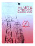
5 Ad-just the voltmeter scale to obtain the most signifi-cant figures Turn o and unplug the power supply; turn o theDMM : Spade Connection to Circuit BoardPART 4: Graphing13. OpenGraphical Analysis. Enter all of your voltageand current data as four separate data sets (one foreach resistor). Include the point (0,0) in each set.[Other graphing software may be used, provided thegraphs include all requisite elements.]14. the three Ohmic resistors on onegraph. Apply a linear fit to each Calculate the resistance of each circuit using theslope of Compare theseRgraphvalues to the measuredReqvalues using the percentdi erence formula (Eq. , Page 155).16. Plot a for the light Print a copy of both 15: Ohm s Law83 QUESTIONS1. Read the information in the next column. Howmuch current would it take to cause pain? Whatwas the maximum current you measured for thisexperiment?2. Why was there no danger to you while you per-formed this Experiment ? The current required forthis Experiment is as high as 30 mA.
6 Some experi-ments will require current as high as A. Explainwhy there will be no danger to you. Read the in-formation in the next column again, more carefullyif Is the graph the light bulb linear?What does this tell you about the resistance of alight bulb as the filament gets hotter?4. Compare the experimental (DMM, graph) values foreach ohmic Do the experimental values fall within the toleranceof the resistors? What might cause the values to ex-ceed the tolerance?6. The power output of a circuit is given by:P=I2R=V2R=IV( )The resistors used in this Experiment are 2-wattresistors. What is the maximum power output ofR1when V is applied across it (use your graphvalue)?7. Calculate the power output of each ohmic resistor(use your graph value) when a potential of Vis Verify, using only the units provided in Table ,that each part of Eq. is equal to J/s. What isthe unit of power output?Can voltage kill you?It s actually current that kills. So why are HazardousVoltage signs so prevalent?
7 Paul Hewitt1explains itvery nicely:Consider Ohm s Law:V=IR. What isthe resistance of your skin? That dependson the state of your skin: dry or wet. Ifit s wet, is it water or sweat? Sweat, ofcourse, contains salt; salt water is a resistance will be dramatically di er-ent for di erent situations! Very dry skinhas a resistance of about 500,000 , whileskin wet with salt water has a resistanceof about 100 . Once the voltage of a de-vice and your skin s resistance are known,we can estimate the current that will flowthrough your ACan be AIs ACauses involuntarymuscle contractions (spasms) ACauses loss of muscle AIf through the heart, causes seriousdisruption; probably fatal ifcurrent lasts for more than 1 secondTable : E ect of Electric Current on the BodyNote that the e ect caused by these currents areap-proximatevalues. It is quite di cult to get volunteersfor this area of research!1 Hewitt, Paul G., ,SanFrancisco.