Transcription of Experiment 16: Series and Parallel Circuits
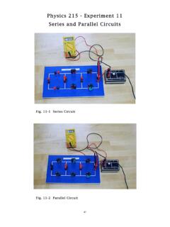
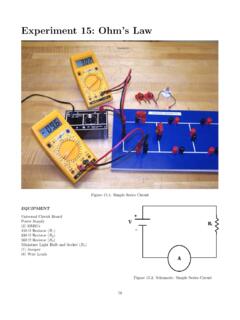
1 84 Experiment 16: Series and Parallel CircuitsFigure : Combination CircuitEQUIPMENTU niversal circuit Board(2) 100- Resistors(2) 200- Resistors(2) 300- Resistors(2) Digital Multi-MetersPower Supply(5) Jumpers(6) Wire LeadsExperiment 16: Series and Parallel Circuits85 Advance ReadingText:Resistors in Series , Parallel , Manual:Appendix CAppendix??- DMMO bjectiveThe objective of this lab is to study Circuits with re-sistors connected in Series , Parallel , and the previous Experiment , you constructed 4 Circuits ,each circuit built with one resistive element. In thisexperiment, you will construct Circuits using first type of circuit you will construct is aseriescircuit(Fig.)
2 And Fig. ). In a Series circuit ,the resistors are connected end-to-end such that thecurrent is the same through each resistor:The currenthas only one path available. The voltage drop acrosseach resistor depends on the resistor a Series circuit , the total equivalent resistance,Reqis:Req=R1+R2+R3+ +RN=N i=1Ri( )(Resistors in Series )Figure : Series circuit SchematicThe second type of circuit you will construct is apar-allel circuit (Fig. and Fig. ). Resistors aresaid to be in Parallel when they are connected to eachother at each end. In this way, the potential differ-ence applied across the combination is the same as thepotential difference applied across an individual resis-tor.
3 The current through each resistor depends on theresistor current has more than one pathavailable and takes all available a Parallel circuit , the total equivalent resistance,Req, is:1 Req=1R1+1R2+1R3+ +1RN=N i=11Ri( )(Resistors in Parallel )Figure : Parallel circuit SchematicThe third type of circuit you will construct is acom-bination circuit (Fig. and Fig. ). Resistiveelements are not connected in Series or Parallel . Tocalculate the total equivalent resistance of a combina-tion circuit , it should first be simplified (reduced to anequivalent resistor,Req). This is done by choosing re-sistors that are connected ineitherseriesorparallel,one step at a time, adding those elements by use ofEq.
4 Or Eq. , then proceeding to the next setof : Combination circuit SchematicNote that it is not correct to, for example, calculatethe resistance of the 3 resistors across the top of thecircuit using Eq. , and then calculate the resistanceofR4,R5, andR6using Eq. You must identifywhich resistors areeitherin parallelorin Series , thenapply the appropriate equation one step at a 16: Series and Parallel CircuitsName:1. What is a Series circuit ? (10 pts)2. What is a Parallel circuit ? (10 pts)3. Is the equivalent resistance,Req, of a Series circuit greater than or less than any individual resistor?(10 pts)4. Is the equivalent resistance,Req, of a Parallel circuit greater than or less than any individual resistor?
5 (10 pts)5. CalculateReqfor each of the first three Circuits shown in Fig. - Fig. using the stated nominal valuesfor resistance. (Show all work on back of this sheet.) (25 pts)6. You will plotI vs. Vfor each of the three Circuits on one graph. What value should each slope have (use thestated values for resistance)? (25 pts)7. CreateData Tablesin your lab notebook for all parts of this Experiment . Sketch the columnheadings on theback of this sheet. (10 pts) Experiment 16: Series and Parallel Circuits87 PROCEDUREPART 1: Series CircuitRecord all data in table that (i= 1, 2, .. , n)1. MeasureRi, then construct a Series circuit (Fig. ) with 100- , 200- , and 300- resistorsand ammeter (200 mA DCA); do not connect thepower supply Draw the schematic using measuredRi Connect the unplugged power supply and the volt-meter (DCV) to your instructor approval of your circuit6.
6 Always be sure the power supply is turned off be-fore you plug it into an outlet. Plug in the powersupply, and set the voltage to V. Measure thecurrent and Record the current (A) and the voltage (V) as youincrease the voltage in V increments up to Leave the voltage at V; disconnect the voltmeterfrom the power supply. Maintaining the same orien-tation of the leads (if clockwise, black follows red), Add these potential differences ( i=1Vi).10. Does i=1 Viequal V? If not, ask your TA 2: Parallel Circuit11. RepeatPart 1,Step 1-Step 8, for the Parallel cir-cuit (Fig. ).12. DoesV2=V1+VA, or doesV2=V1=V3? Areeach of these values negative or positive?
7 !Yes, itmatters!13. DoesV=|V1+VA|?PART 3: Combination Circuit14. RepeatPart 1,Step 1-Step 8, for the combinationcircuit (Fig. ).PART 4: Graphing15. GraphI vs. Vfor each of the first three Circuits onone graph (Part 1,Part 3, andPart 4). 5of this Experiment may also be on an certain you know how to produce a completegraph. Ask for help if Why should the voltage drops (electric potential dif-ferences) across the resistors connected in parallelbe the same? Were your values equal?2. Calculate the equivalent resistance of each of thefirst three Circuits you constructed for this experi-ment using your measured values. Show each stepin this process (math and schematic).
8 Rememberto includeRAin your Consider your data fromPart 2. Create a table sim-ilar to the one shown below. Why doesReqchangewhen you change the scale of the ammeter?Ammeter ScaleReqRANo Ammeter20 A200 A2mA20mA200mA2 A20 A