Transcription of Chapter 6: Series-Parallel Circuits - UMass Lowell
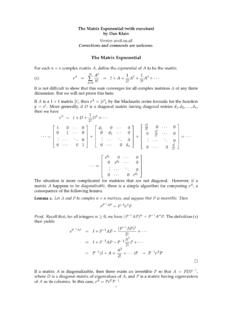
1 Learning with PurposeSlide 1 Learning with PurposeSlide 1 Chapter 6: Series-Parallel CircuitsInstructor: Jean-Fran ois with PurposeSlide 2 Identifying Series-Parallel relationshipsMost practical Circuits have combinations of series and parallel that are connected in series will share a common path. Components that are connected in parallel will be connected across the same two with PurposeSlide 3 Combination circuitsMost practical Circuits have various combinations of series and parallel components. You can frequently simplify analysis by combining series and parallel important analysis method is to form an equivalent circuit . An equivalent circuit is one that has characteristics that are electrically the same as another circuit but is generally with PurposeSlide 4 Identifying Series-Parallel relationshipsLearning with PurposeSlide 5 Identifying Series-Parallel relationshipsLearning with PurposeSlide 6 Identifying Series-Parallel relationshipsLearning with PurposeSlide 7 Identifying Series-Parallel relationshipsLearning with PurposeSlide 8 ExamplesRT =R1 + R5 + R4 || (R2 + R3)RT =R1 + R2 || R3 + R4 || R5 Learning with PurposeSlide 9 Total resistanceIdentifying the componentsTotal resistance RT=R1 + R2 || R3= 10 + 50 = 60 WLearning with PurposeSlide 10 ExampleFind RT= 148 WLearning with PurposeSlide 11 Ohm s law.
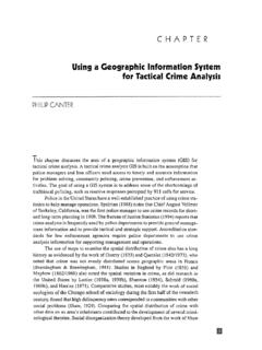
2 = Find I4 = mA (I2 = mA)Total Current5 VLearning with PurposeSlide 12 Find RAB, RBC& RTFind V1, V2, V3, V4, and V5 Voltage RelationshipsV1 = V2 = VV3 = VV4 = VV5 = VLearning with PurposeSlide 13 Learning with PurposeSlide 14 Used to precisely measure resistanceUsed also in conjunction with transducersTransducer= sensor. Change physical parameter in resistance, for WHEATSTONE BRIDGESir Charles Wheatstone, 1802-1875 Learning with PurposeSlide 15 Balanced bridge when the outputVOUT= 0 VWe have then V1=V2and V3=V4 Therefore 1 3= 2 4and 1 1 3 3= 2 2 4 4 Since 1= 3and 2= 4We got 1 3= 2 4and finally 1= 3 2 4 Bridge to find an unknown resistanceTHE WHEATSTONE BRIDGEThe balanced bridgeLearning with PurposeSlide 16 Determine the value of RX. The bridge is balanced (VOUT= 0 V) when RVis set at 1200 W = V 2 4=1200 150100=1800 THE WHEATSTONE BRIDGEE xampleLearning with PurposeSlide 17 Unbalanced bridge when the outputVOUT 0 VUsed to measure several types of physical quantities such as mechanical strain, temperature, or the transducer in one leg of the WHEATSTONE BRIDGEThe unbalanced bridgeThe resistance of the transducer changes proportionally to the changes in the parameter that it is the bridge is balanced at a known point, then the amount of deviation indicates the amount of change in the parameter being , the value of the parameter being measured can be determined by the amount that the bridge is unbalancedLearning with PurposeSlide 18 Determine the output voltage of the temperature-measuring bridge circuit if the thermistor is exposed to a temperature of 50 C and its resistance at 25 C is k.
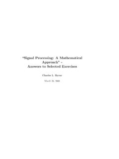
3 Assume the resistance of the thermistor decreases to 900 at 50 WHEATSTONE BRIDGEE xampleAt 25 C the bridge is 50 C the bridge is unbalanced. We can apply the voltage-divider formula to the left and right sides. = 3 3+ =1 1 +900 12 = = 4 2+ 4 =1 2 12 =6. VOUT= VA-VB = = V at 50 CLearning with PurposeSlide 19 Learning with PurposeSlide 20 What for ?To simplify Electric Engineer s Life !!!Simplify a complicate Series-Parallel circuit into an equivalent circuitConsists of an equivalent voltage source VTHAnd an equivalent resistance RTHTHEVENIN s TheoremL on Charles Th venin, French Engineer, 1857-1926 Learning with PurposeSlide 21 The Theveninequivalent voltage VTHis the open circuit (no-load) voltage between two specified output terminals in a Theveninequivalent resistance RTHis the total resistance appearing between two specified output terminals in a circuit with all sources replaced by their internal resistances (which for an ideal voltage source is zero).
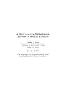
4 THEVENIN s TheoremLearning with PurposeSlide 22 Step 1: Find VTH = Find the voltage between A and BThree steps: #1 Output terminalsCircuit complicate Learning with PurposeSlide 23 Step 2: Find RTHS hort-circuiting the batteryFind the resistance between A and BThree steps: #2 Learning with PurposeSlide 24 Step 3: Combining both VTHand RTHT heveninequivalent circuit Three steps: #3 Learning with PurposeSlide 25 Depends on the viewpointLearning with PurposeSlide 26 Depends on the viewpointLearning with PurposeSlide 27 Thevenizinga Bridge CircuitLearning with PurposeSlide 31 Learning with PurposeSlide 32 For a given source voltage, maximum power is transferred from a source to a load when the load resistance is equal to the internal source power is transferred to the load when RL= Power Transfer TheoremLearning with PurposeSlide 33 Example: Determine the load power for different values of the variable load resistance [0:125] WSolution: Using Ohm s law and Power FormulaFor RL= 0 W = + =1075+0=133 = 2 =1332 0=0 Maximum Power Transfer TheoremLearning with PurposeSlide 34 Maximum Power Transfer TheoremFor RL= 0 W : PL= 0 WFor RL= 25 W : PL= 250 mWFor RL= 50 W : PL= 320 mWFor RL= 75 W.
5 PL= 334 mWFor RL= 100 W : PL= 326 mWFor RL= 125 W : PL= 313 mWRL(W)0255012510075100200300400PL(mW)Ma ximum for RL=RSNote that RS= RTHif we are using the Thevenin sTheoremLearning with PurposeSlide 35 What is happening when there are two or more voltage sources ???How do we calculate I2 ???Superposition TheoremLearning with PurposeSlide 36 Superposition TheoremProblem: Find I2 Determine RT1and IT1 ThenI2(S1)Determine RT2and IT2 ThenI2(S2)I2 = I2(S1)+I2(S2)Learning with PurposeSlide 37 Find I2, the current through R21_ short replace VS2, find RT1, then IT1and finally I2(S1)RT1=232 W// IT1= mA // I2(S1)= mA2_ short replace VS1, find RT2, then IT2and finally I2(S2)RT1=399 W // IT1= mA // I2(S1)= mAI2 = I1(S1)+ I2(S2)= + = mASuperposition TheoremExampl