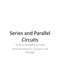
5 Series And Parallel Circuits
Found 8 free book(s)
EE301 - PARALLEL CIRCUITS AND KIRCHHOFF’S CURRENT …
www.usna.eduHomes and ships are usually wired in parallel instead of in series. The reason: The parallel circuit will continue to operate even though one component may fail open. All components can operate at rated voltage independent of other loads when wired in parallel. Series - Parallel Circuits Circuits may contain a combination of series and parallel ...

RLC Resonant Circuits - University of Cambridge
mlg.eng.cam.ac.ukFor the simple parallel RLC circuit shown in gure 5 this is just equal to the rms supply voltage but for the series RLC circuit it is given by a potential divider rule. Therefore, for series circuits it is in general simpler to calculate the max energy stored by considering the inductor and in parallel circuits by considering the capacitor.
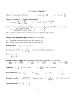
ELECTRONIC FORMULAS - TSCM
tscm.com2 (for series circuit ) Z ’ RX R 2%X (for R and X in parallel ) Q ’ X L R or X C R 2-7.1 ELECTRONIC FORMULAS Ohm's Law Formulas for D-C Circuits. Ohm's Law Formulas for A-C Circuits and Power Factor. In the above formulas 1 is the angle of lead or lag between current and voltage and cos 1 = P/EI = power factor or pf.
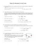
Chapter 24: Alternating-Current Circuits
www.csun.edu: V I X 5.68 mA 9.42 54 mV 7. Multiply the current by the capacitive reactance: rms, rmsCC: V I X 5.68 mA 17.68 k 100 V 0.10 kV 50. The image shows an inductor (L = 0.22 mH) in series with a 15-Ω resistor. These elements are in parallel with a second 15-Ω resistor. An ac generator powers the circuit with an rms voltage of 65 V.

Series -Parallel Circuits - Oakton Community College
www.oakton.eduOverview of Series-Parallel Circuits A series-parallel circuit, or combination circuit, combines both series and parallel connections. Most electronic circuits fall into this category. Series-parallel circuits are typically used when different voltage and current values are required from the same voltage source. Series components form a series ...
Series and Parallel Circuits - Electronics
cie-wc.eduSeries-Parallel Circuits • Series-Parallel circuits can be more complex as in this case: In circuit (a) we have our original complex circuit. In circuit (b) we have resistors R 1 and R 2 combined to get 13.2Ω. R 4 is in series with the newly combined R 12 and their added value is 51.2Ω. And now (c) we are left with R 124 in parallel with R 3.

Capacitor and inductors - MIT OpenCourseWare
ocw.mit.eduCapacitors connected in series and in parallel combine to an equivalent capacitance. Let’s first consider the parallel combination of capacitors as shown on Figure 5. Note that all capacitors have the same voltage, v, across them. i(t) v(t) v +-C1 C2 C3 Cn - - - - - - i1 i2 i3 in Figure 5. Parallel combination of capacitors.
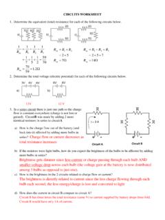
Circuit A Circuit B - Livingston Public Schools
www.livingston.orgTotal 6.00 1.1 5.5 (V bat /I bat) 6.6 g) How does the voltage drop across each branch in a parallel circuit compare? The voltage drop across each branch is the SAME in a parallel circuit. h) If the resistors were light bulbs, explain in terms of charge flow (current) and energy per charge (voltage) which bulb would be brightest / dimmest.
Similar queries
Parallel circuits, Parallel, Series, Parallel Circuits Circuits, Series and parallel, RLC Resonant Circuits, Series circuits, ELECTRONIC FORMULAS, Formulas, Circuits, Chapter 24: Alternating-Current Circuits, Series -Parallel Circuits, Oakton Community College, Series-parallel circuits, Series and Parallel Circuits, MIT OpenCourseWare