Series And Parallel Resistive Circuits
Found 11 free book(s)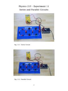
Physics 215 - Experiment 11 Series and Parallel Circuits
www.phy.olemiss.eduSeries and Parallel Circuits 44 + V - 2 The third type of circuit you will construct is a ccombination circuit (Fig. 11-3 and Fig. 11-6). Resistive elements are not connected in series or parallel. To analyze this type of circuit, it should first be simplified (reduced to an equivalent resistor, Req). R Fig. 11-6: Combination Circuit Schematic ...
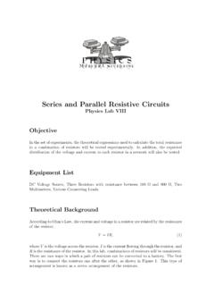
Series and Parallel Resistive Circuits - Mercer University
physics.mercer.eduSeries & Parallel Resistive Circuits 5 Series Combinations In this set of experiments, the total resistance of resistors in a series combination will be measured. In addition, measurements will be made to check the validity of the as-sumptions used to derive the theoretical expression for the total resistance of a series combination. 1.

RLC Resonant Circuits - University of Cambridge
mlg.eng.cam.ac.ukFor the simple parallel RLC circuit shown in gure 5 this is just equal to the rms supply voltage but for the series RLC circuit it is given by a potential divider rule. Therefore, for series circuits it is in general simpler to calculate the max energy stored by considering the inductor and in parallel circuits by considering the capacitor.
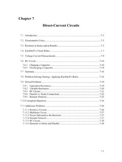
Chapter 7 Direct-Current Circuits
web.mit.edu7.3 Resistors in Series and in Parallel The two resistors R1 and R2 in Figure 7.3.1 are connected in series to a voltage source∆V. By current conservation, the same current I is flowing through each resistor. Figure 7.3.1 (a) Resistors in series. (b) Equivalent circuit.
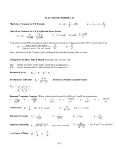
ELECTRONIC FORMULAS - TSCM
tscm.com2 (for series circuit ) Z ’ RX R 2%X (for R and X in parallel ) Q ’ X L R or X C R 2-7.1 ELECTRONIC FORMULAS Ohm's Law Formulas for D-C Circuits. Ohm's Law Formulas for A-C Circuits and Power Factor. In the above formulas 1 is the angle of lead or lag between current and voltage and cos 1 = P/EI = power factor or pf.
Intro to Electricity
engineering.nyu.eduSeries Connection of Cells • Each cell provides 1.5 V • Two cells connected one after another, ... circuits. •Henceforth, the conductors that exhibit the property of resisting current flow are ... the resistive material and tap off the desired resistance.
AC Electrical Circuit Analysis
www2.mvcc.eduin a circuit, as well as between currents or resistive/reactive values. Many of the topics in this text will echo your studies in DC circuit analysis, such as Ohm's law, Kirchhoff's voltage and current laws, series-parallel analysis, nodal analysis, and the like.
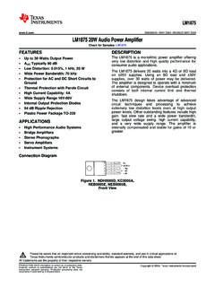
LM1875 20W Audio Power Amplifier datasheet (Rev. A)
www.ti.com• Protection for AC and DC Short Circuits to supplies, over 30 watts of power may be delivered. ... least 1Ω) should be placed in series with the output of the LM1875. A method commonly employed to protect amplifiers from low impedances at high frequencies is to couple to the load through a 10Ωresistor in parallel with a 5 μH inductor.
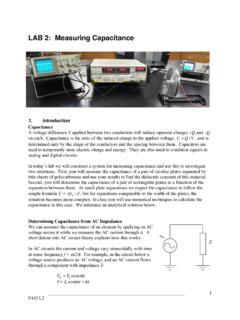
LAB 2: Measuring Capacitance
d32ogoqmya1dw8.cloudfront.netideal resistor and capacitor in series. The capacitance is due to the parallel plates (plus stray capacitance from other parts of the circuit). The resistance includes the resistance of the wires and the output impedance of the AC voltage source. If there were no resistive component to the circuit, then the ratio of the current to voltage would
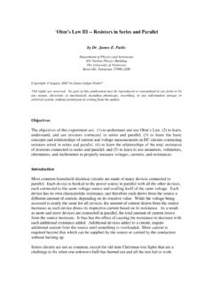
`Ohm’s Law III -- Resistors in Series and Parallel
www.phys.utk.eduOhm’s Law III—Resistors in Series and Parallel V RRR 2 1 2 3 E V 1 V 3 V T I 1 I I T 2 I 3 Figure 1. Three resistors R1, R2, and R3 connected in series. The voltage drop across the battery VT will be the total sum of the individual drops across each of the 3 resistors, and

Chapter 12 Alternating-Current Circuits
web.mit.edu12.2 Simple AC circuits Before examining the driven RLC circuit, let’s first consider the simple cases where only one circuit element (a resistor, an inductor or a capacitor) is connected to a sinusoidal voltage source. 12.2.1 Purely Resistive load Consider a purely resistive circuit with a resistor connected to an AC generator, as shown
Similar queries
Physics 215 - Experiment 11 Series and Parallel Circuits, Series and Parallel Circuits, Resistive, Series, Parallel, Series and Parallel Resistive Circuits, Parallel Resistive Circuits, Circuits, Series circuits, Parallel circuits, Chapter 7 Direct-Current Circuits, ELECTRONIC FORMULAS, Formulas, AC Electrical Circuit Analysis, Capacitance, Series and Parallel