Transcription of Series and Parallel Resistive Circuits - Mercer University
1 Series and Parallel Resistive CircuitsPhysics Lab VIIIO bjectiveIn the set of experiments, the theoretical expressions used to calculate the total resistancein a combination of resistors will be tested experimentally. In addition, the expecteddistribution of the voltage and current to each resistor in a network will also be ListDC Voltage Source, Three Resistors with resistance between 100 and 900 , TwoMultimeters, Various Connecting BackgroundAccording to Ohm s Law, the current and voltage in a resistor are related by the resistanceof the resistor,V=IR,(1)whereVis the voltage across the resistor,Iis the current flowing through the resistor, andRis the resistance of the resistor. In this lab, combinations of resistors will be are two ways in which a pair of resistors can be connected to a battery. The firstway is to connect the resistors one after the other, as shown in Figure 1. This type ofarrangement is known as aseriesarrangement of the & Parallel Resistive CircuitsFigure 1: Series Combination of ResistorsIn this case, the same current flows through both resistors while the voltage from thebattery is split between the two resistors,Itotal=I1=I2, Vtotal=V1+V2.
2 (2)In this equation,I1is the current through the first resistor,I2is the current throughthe second resistor,Vtotalis the total voltage supplied by the battery,V1is the voltageacross the first resistor, andV2is the voltage across the second resistor. SubstitutingOhm s Law into the voltage condition, and noting that the same current flows throughthe circuit , givesItotalRtotal=I1R1+I2R2= Rtotal=R1+R2.(3)In this equation,R1is the resistance of the first resistor andR2is the resistance of thesecond resistor. For more than two resistors, the total resistance is just the sum of theindividual resistances,Rtotal, Series =R1+R2+R3+..=N i=1Ri.(4)The other possible combination of two resistors involves connecting the ends of theresistors to the battery. This arrangement, shown in Figure 2, is known as 2: Parallel Combination of ResistorsIn this case, the voltage across each resistor is equal to the voltage of the batterywhile the total current in the circuit is split between the two resistors,Vtotal=V1=V2, Itotal=I1+I2.
3 (5)v:F06 Series & Parallel Resistive Circuits3 Substituting Ohm s Law into the current condition, and noting that all of the voltagesare the same, yields,VtotalRtotal=V1R1+V2R2= 1 Rtotal=1R1+1R2.(6)For more than one resistor in Parallel , based upon this relation, the inverse of the totalresistance is the sum of inverses of the individual resistors,1 Rtotal, Parallel =1R1+1R2+1R3+..=N i=11Ri.(7)In this set of experiment, these theoretical expressions for the total resistance of a com-bination of resistors will be tested, along with the conditions that were used to ResistorsIn this section, the resistance of the individual resistors will be colors on each resistor indicate, roughly, the resistance of each resistor. Thecolor of the band closest to the end of the resistor gives the first digit of theresistance. The color of the next band gives the second digit of the resistance. Thethird band color is the power of ten that multiplies the digits indicated by the firsttwo bands.
4 The last band indicates the error, as a percentage, in the resistance. Usethis information, along with Table 1, to determine the resistance of each resistor,and the uncertainty in the resistance, based upon the color code. Record the valueof the resistance and the uncertainty on your data (%)Black01 Brown1101 Red2102 Orange3103 Yellow4104 Green5105 Blue6106 Violet7107 Grey8108 White9109 Gold10 15 %Silver10 210 %Colorless20 %Table 1: Color Code for Resistorsv:F064 Series & Parallel Resistive making any connections, make sure the power supply is the first resistor first to the voltage supply, next to the multimeterbeing used as an ammeter, and then to the multimeter being used as a circuit should be similar to the circuit diagram in Figure 3. It may be of someuse for you to connect the voltmeter last when wiring the 3: circuit Diagram for Individual Resistor the power supply turned off, turn the current control on the power supply tohalf its maximum value.
5 Turn the voltage control completely down to zero beforeturning the power on. The voltmeter should be set to the 20 V (DC) maximumscale, and the ammeter should be set to the 200 mA (DC) maximum the power on, and increase the voltage slowly until one volt is displayed onthe voltmeter. Record the voltage and the current displayed from each meter onyour data slowly increasing the voltage until you have voltage and current measure-ments for 2 V, 3 V, 4 V, and 5 the voltage to zero and turn the power supply off. Disconnect the firstresistor. Connect the second resistor to the power supply and multimeters. Repeatthe process outlined above for the second obtaining the current and voltage measurements for the second resistor, repeatthe above process for the third each of the resistors, use the voltage and current measurements, and Ohm sLaw, to calculate the resistance of each resistor. For each resistor, calculate andrecord the average resistance values. The average resistance will be used to calculatethe theoretical value of the resistance for combinations of each resistor, calculate the percent variation in the ariation= 100 Largest V alue Smallest V alue2 Average V alue(8)v:F06 Series & Parallel Resistive Circuits5 Series CombinationsIn this set of experiments, the total resistance of resistors in a Series combination willbe measured.
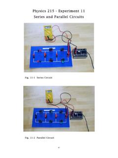
6 In addition, measurements will be made to check the validity of the as-sumptions used to derive the theoretical expression for the total resistance of a making any connections, make sure the power supply is the first and second resistors in Series . Connect the Series combinationfirst to the voltage supply, next to the multimeter being used as an ammeter, andthen to the multimeter being used as a voltmeter. Your completed circuit shouldbe similar to the circuit diagram in Figure 4. It may be of some use for you toconnect the voltmeter last when wiring the 4: circuit Diagram for Series Resistors the power supply turned off, turn the current control on the power supply tohalf its maximum value. Turn the voltage control completely down to zero beforeturning the power on. The voltmeter should be set to the 20 V (DC) maximumscale, and the ammeter should be set to the 200 mA (DC) maximum the power on, and increase the voltage slowly until one volt is displayed onthe power supply.
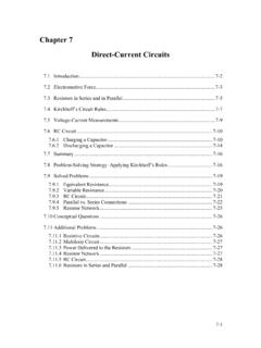
7 Record the voltage and the current displayed on each meter onyour data slowly increasing the voltage until you have voltage and current measure-ments for 2 V, 3 V, 4 V, and 5 the voltmeter. Use the voltmeter to measure the voltage drop acrosseach individual resistor for the last trial, when the total voltage is about 5 V. Recordthese voltages on your data sheet. In addition, record the total voltageVTotalandthe total currentITotalin the the voltage to zero and turn the power supply off. Disconnect the resistors,and connect the second and third resistors in Series . Connect the Series combinationto the power supply and multimeters according the circuit diagram above. Repeatthe process outlined above for this second Series :F066 Series & Parallel Resistive CircuitsParallel CombinationIn this set of experiments, the total resistance of resistors in a Parallel combination will bemeasured. In addition, measurements will be made to check the validity of assumptionsused to derive the theoretical expression for the total resistance of a Parallel making any connections, make sure the power supply is the first and second resistors in Parallel .
8 Connect the Parallel combi-nation first to the voltage supply, next to the multimeter being used an ammeter,and then to the multimeter being used as a voltmeter. Your completed circuitshould be similar to the circuit diagram in Figure 5. It may be of some use for youto connect the voltmeter last when wiring the 5: circuit Diagram for Parallel Resistors the power supply turned off, turn the current control on the power supply tohalf its maximum value. Turn the voltage control completely down to zero beforeturning the power on. The voltmeter should be set to the 20 V (DC) maximumscale, and the ammeter should be set to the 200 mA (DC) maximum the power on, and increase the voltage slowly until around one volt is displayedon the voltmeter. Record the voltage and the current displayed on each meter onyour data slowly increasing the voltage until you have voltage and current measure-ments for about 2 V, 3 V, 4 V, and 5 the voltmeter. Use the voltmeter to measure the voltage drop acrosseach individual resistor for the last trial, when the total voltage is about 5 V.
9 Recordthese voltages on your data sheet. In addition, record the total voltageVTotalandthe total currentITotalin the the voltage to zero and turn the power supply off. Disconnect the resistors,and connect the second and third resistors in Parallel . Connect the Parallel combi-nation to the power supply and multimeters according the circuit diagram the process outlined above for this second Parallel :F06 Series & Parallel Resistive Circuits7 Series and Parallel CombinationIn this set of experiments, the total resistance of resistors in a Parallel and Series combi-nation will be measured. In addition, measurements will be made to check the validityof assumptions used to derive the theoretical expression for the total resistance of making any connections, make sure the power supply is the first, second, and third resistors in a Series and Parallel com-bination as indicated in Figure 6. Connect the combination first to the voltagesupply, next to the multimeter being used an ammeter, and then to the multimeterbeing used as a voltmeter.
10 Your completed circuit should be similar to the circuitdiagram in Figure 6. It may be of some use for you to connect the voltmeter lastwhen wiring the 6: circuit Diagram for Parallel and Series Resistor Combination the power supply turned off, turn the current control on the power supply tohalf its maximum value. Turn the voltage control completely down to zero beforeturning the power on. The voltmeter should be set to the 20 V (DC) maximumscale, and the ammeter should be set to the 200 mA (DC) maximum the power on, and increase the voltage slowly until around one volt is displayedon the power supply. Record the voltage and the current displayed on each meteron your data slowly increasing the voltage until you have voltage and current measure-ments for about 2 V, 3 V, 4 V, and 5 the voltmeter. Use the voltmeter to measure the voltage drop acrosseach individual resistor for the last trial, when the total voltage is about 5 V. Recordthese voltages on your data sheet.