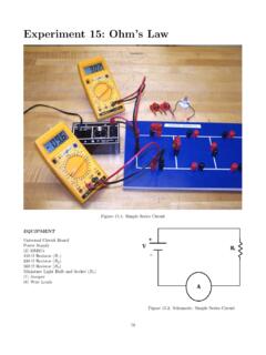
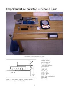
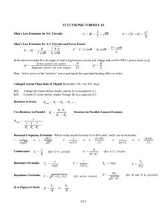
Transcription of Physics 215 - Experiment 11 Series and Parallel Circuits
1 Physics 215 - Experiment 11 Series and Parallel Circuits 41 Fig. 11-1 Series circuit Fig. 11-2 Parallel circuit Physics 215 - Experiment 11 Series and Parallel Circuits 42 Fig. 11-3 Combination circuit Equipment Universal circuit board 2 100- Resistors 2 200- Resistors 2 330- Resistors 2 Digital Multi-Meters (DMM's) Power Supply 5 Jumpers Wire Leads Physics 215 - Experiment 11 Series and Parallel Circuits 43 + V - Advance Reading Urone, Chapter 20, sections 20-1 & 20-4. Appendix B Computers and Software Appendix C Equipment: DMM. Objective: The objective of this lab is to study resistances connected in Series , Parallel , and combination Circuits .
2 Theory: In the previous Experiment you constructed a circuit that contained only one resistive element, a resistor or a light bulb. In this Experiment you will construct Circuits using multiple resistors. The first type of circuit you will construct is a Series circuit (Fig. 11-1 and Fig. 11-4). In a Series circuit the resistors are connected end-to-end such that the current is the same through each resistor; the current has only one path available. The voltage drop across each resistor depends on the resistor value. For a Series circuit the total equivalent resistance, Req, is: Req = R1 + R2 + R3 + .. + RN = Rii=1N (Eq.)
3 11-1: Resistors in Series ) The second type of circuit you will construct is a pparallel ccircuit (Fig. 11-2 and Fig. 11-5). Resistors are said to be in Parallel when they are connected at both ends, such that the potential difference applied across the combination is the same as the potential difference applied across an individual resistor. The current through each resistor depends on the resistor value. The current has more than one path available, and takes all available paths. For a Parallel circuit the total equivalent resistance, Req, is: 1 Req=1R1+1R2+1R3+..+1RN=1 Rii=1N (Eq. 11-2: Resistors in Parallel ) Fig.
4 11-4: Series circuit Schematic R3 R1 R2 A I Physics 215 - Experiment 11 Series and Parallel Circuits 44 + V - The third type of circuit you will construct is a ccombination circuit (Fig. 11-3 and Fig. 11-6). resistive elements are not connected in Series or Parallel . To analyze this type of circuit , it should first be simplified (reduced to an equivalent resistor, Req). Fig. 11-6: Combination circuit Schematic WARNING! Have your instructor approve each circuit before you plug in a power supply! Be sure the power supply is turned off before you plug it in. Procedure Series circuit 1. Measure the resistance of each resistor, Ri, (Fig.)
5 C-14); record the values. 2. Construct a Series circuit (Fig. 11-4) with the power supply (unplugged from outlet) and three resistors (one each: 100- , 200- , 330- ) connected in the appropriate places. (Note: There is more than one way to do this.) 3. Calculate the theoretical value of the equivalent resistance, Req-T, of the circuit . (Eq. 11-2. Use the measured values of R.) Record Req-T. 4. Select the voltmeter function of one DMM (Fig. C-9); connect it to your circuit so that it will measure the potential difference when a current is flowing (Fig. C-12). Select the ammeter function (Fig. C-11) on the second DMM; insert it into your circuit (Fig.
6 C-15). Get instructor approval of your circuit ! R1 Fig. 11-5: Parallel circuit Schematic A R2 R3 + V - A R1=330 R2=200 R3=100 R4= 100 R5= 200 R6= 330 + V - Physics 215 - Experiment 11 Series and Parallel Circuits 45 5. Plug in the power supply. Adjust the power supply until the potential difference across the resistors is ; this is the same as the potential difference across the power supply. Record the current (A) and the voltage (V). Repeat this process in increments up to 6. With the voltage across the power supply set at , disconnect the voltmeter. Maintaining the same orientation of the leads (black lead behind red lead), measure the potential difference across each resistor.
7 Add these potential differences (Vii=1N ). 7. Does Vii=1N equal 8. Turn off, then disconnect, the power supply from the circuit . Measure and record the resistance of the circuit , Req, (Fig. C-10 and Fig. C-13) with the ohmmeter function of the DMM. Determine Resistance of Ammeter 9. Leave the power supply disconnected. Set the ohmmeter scale to 2k and the ammeter scale to 200 A. Measure and record Req of the circuit . 10. Measure and record Req for each of the following scale settings on the ammeter: "2m","20m","200m" and 20A . (Note-you will have to change DMM positive lead to 20A hole for last measurement).
8 Parallel circuit 11. Construct a Parallel circuit (Fig. 11-5) with the power supply (unplugged from outlet) and three resistors (one each: 100 , 200 , 330 . There are a variety of ways to do this. 12. Calculate Req-T of the circuit . 13. Connect the voltmeter and ammeter to the circuit . Plug in the power supply and increase the power until the potential difference is Record the voltage and current. 14. Measure and record the potential difference across each resistor. 15. As you increase the potential difference, in increments, up to , measure and record the voltage and current. 16. Turn off, then disconnect, the power supply from the circuit .)
9 Measure and record Req of the circuit . Combination circuit 17. Construct a combination circuit (Fig. 11-6). 18. Calculate Req-T. 19. Measure and record Req of the circuit . 20. Set the potential difference to As you increase the potential difference, in Physics 215 - Experiment 11 Series and Parallel Circuits 46 increments, up to , measure and record the voltage and current. Test circuit 21. Your TA will draw a schematic on the board. Construct this circuit . Set the voltage as specified by the TA. 22. Measure I, Ri, Vi, and Req. Graphing 23. On one graph, graph I vs. V for each of the Circuits . From this graph, determine Req for each circuit (use Linear Fit).
10 Questions 1. Draw an equivalent circuit for each of the three Circuits you constructed for this Experiment . Show each step in this process. 2. Why should the voltage drops (potential differences) across the resistors connected in Parallel be the same? Were your values equal? 3. Are the Circuits in houses wired in Series and/or Parallel ? What evidence do you have for your answer? 4. Consider your data from Determine Resistance of Ammeter. Why does Req change when you change the scale of the ammeter?