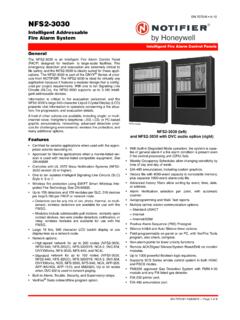
Transcription of The EN54 Part 2, 4 and 13 Fire System - Advanced
1 Scope of work: To design, supply, install and commission an Analogue Addressable Fire Alarm Control System in accordance with the details specified herein and in accordance with supplied drawings CSD-005-04 2 The EN54 Part 2, 4 and 13 Fire System The System shall include all materials, equipment and wiring required to install the complete Fire Detection and Alarm System . The System shall include but not be limited to one or more control panels, repeater panels, sensors, call points, audible and visual alarm indicating devices and relays. The System components shall be freely available from a number of sources, ( not a closed protocol System ), and shall support at least Apollo Discovery, Xplorer, XP95, S90 and Xpander Devices, Argus Vega, Hochiki ESP and Nittan Evolution protocol.
2 The installation shall include the laying of all cables required for connection of the detection, alarm indicating and other devices along with connections to the power supply as appropriate to the design. All cabling shall conform to the requirements and recommendations of the Fire Alarm Control Panel manufacturer. Any openings /chasings in walls, ceilings or floors shall be made good. The System shall be designed such that no more than 80% of the available signalling / detection loop capacity is employed to allow for future requirements. Normative references: EN54-1:2011 Introduction EN54-2:1997 +A1:2006 Control and Indicating Equipment EN54-3:2001 +A1:2002 +A2:2006 Audible Alarm Devices EN54-4:1997 +A1:2002 +A2:2006 Power Supply Equipment EN54-5:2000 +A1:2002 Heat detectors Point detectors EN54-7:2000 +A1:2002 +A2:2006 smoke detectors Point detectors EN54-11:2001 +A1:2005 Manual Call Points EN54-13:2005 Compatibility Assessment of System Components EN54-17:2005 Short Circuit Isolators EN54-18:2005 Input / Output Devices EN54-23:2010 Visual Alarm Devices EN54-25:2008 Components using Radio Links BS5839-1.
3 2013 Code of practice CSD-005-04 3 Standards The fire detection System shall be designed, installed and commissioned in accordance with, and all elements shall meet the requirements of BS5839-1 Code of Practice. The responsible company should be able to demonstrate their competence to design, install and commission the System , by certification to BAFE SP203, LPS1014 or other relevant standard. The equipment manufacturer shall operate a quality management System in accordance with ISO 9001. In addition, the equipment shall be manufactured under a recognised factory control procedure such as the Vertrauen durch Sicherheit (VDS) scheme. All detection devices shall be independently certified as complying with the relevant EN54 standard. The Fire Alarm Control Panel shall be independently certified as complying with requirements of EN54 Part 2, EN54 Part 4 and EN54 Part 13.
4 The Independent approvals body shall be the British Standards Institute (BSI) and Vertrauen durch Sicherheit (VDS). In addition to the basic requirements of EN54, the Fire Alarm Control Panel shall offer the following EN54 optional features with requirements: Optional Functions: EN54-2 Clause Indication - Fault signals from points Outputs -Outputs to fire alarm devices Outputs -Outputs to fire alarm routing equipment Outputs -Outputs to fire alarm protection equipment Controls -Investigation delays to outputs Co-incidence detection Alarm Counter Disablement of points Test condition 10 Standardised I/O 11 Power Supply Equipment Functions: EN54-4 Clause Operation from a main power supply Operation from a standby battery Monitor and charge the standby battery Recognise and notify supply faults Compatibility of System components EN54-13 Clause Basic System Requirements Network Systems Components Transmission Path Input and Output Devices linked to fire protection systems CSD-005-04 4 The Fire Alarm Control Panel shall also support a number of additional functions that are not covered by EN54.
5 These additional functions shall include: Programmable Cause / Effect on Outputs ( Phased Evacuation) Auxiliary Power Supply Output Auxiliary Relay Outputs Programmable Push Buttons More Alarms Button Printer Option USB and RS232 Port CSD-005-04 5 Fire Alarm Control Panel (FACP) Functional Description The FACP shall be the central controller of the complete System . It shall receive and process analogue information from the detection devices, provide audible and visual indication of alarm and other conditions to the user, automatically initiate alarm response sequences and provide the user interface for interrogation and user programming of the System . Updates to the FACP operating software shall be simple to undertake and shall not require the use of replaceable components.
6 The operating program and configuration memory shall be stored in non-volatile memory and shall not rely on batteries for retention. The FACP shall incorporate separate microprocessors for signalling loop control and central operation. The FACP shall provide a user interface from which; controls can be operated, manual operations can be carried out, indications are audible and/or visible and System information can be obtained. It shall also be capable of unambiguously indicating the following functional conditions: Quiescent condition, fire alarm condition, fault warning condition and disablement condition. Furthermore, the fire alarm condition shall always be capable of clearly being indicated without any prior manual intervention at the FACP.
7 The FACP shall be easy to configure all basic operating characteristics and variables through the user interface on the FACP to satisfy the detection zone and output mapping of the premises. A PC Tool operating under the Windows operating System shall also be available to fully program the panel. The FACP shall support up to 126/127 Devices (Apollo/Hochiki) or 240 Devices for AV or 254 Devices for Nittan on the signalling loop. The FACP shall fully support the sub-addressing capabilities of the relevant input and output devices. The FACP shall contain one, one to two, or one to four signalling loop drivers depending on the System design requirements. Each signalling loop shall be capable of supplying at least 500mA of power for loop-based sounders or other output devices.
8 The Fire Alarm Control Panel software and hardware loop driver, without modification, shall be compatible with the analogue detection, call points, input and output devices available from, at least, the following manufacturers: Apollo S90, XP95, Discovery, Xplorer and Xpander ranges AV Argus Vega Range Hochiki Enhanced System Protocol ESP Range Nittan Evolution Range The FACP shall fully support the sub-addressing capabilities of loop devices incorporating this feature and any radio based devices within each protocol. The FACP must provide System integrity and is to be approved to EN54 Part 13 thus ensuring:- Enhanced monitoring of ALL circuits including sounder circuits and loop circuits The FACP can detect a fault which may not be visible until an alarm condition Can be selected / programmed for specified current consumption for individual circuits The FACP shall provide 2 or 4 monitored outputs to fire alarm devices, each rated at 1-ampere.
9 An auxiliary supply output shall also be available to provide power for internal option modules. The FACP shall provide a diagnostic monitoring feature for all signalling loop, alarm device output and auxiliary supply output circuits to monitor voltage, current load, etc. This information shall be documented and available to view at Level 2. In addition, diagnostic monitoring of the signalling loop return current pulses shall be provided at Level 3. The FACP shall provide an internal Scope for all signalling loop devices. This information shall be captured and available to view at Level 3 menu only. The FACP shall incorporate a real-time clock for time stamping of events in the event history log and for scheduling of time related functions.
10 CSD-005-04 6 It shall be possible to install a network communications card to allow connection of up to 200 control panels, remote terminals, mimic displays or other peripheral devices. The network shall offer peer-to-peer operation and have a fault tolerant capability. The time to propagate a fire alarm condition across the network shall not exceed 3 seconds. A single FACP shall have the capability for configuration and operation of 200 fire alarm zones. In a network System , the overall System shall have the capability for up to 2000 zones. It shall be possible to adjust sensitivity settings for all detection devices based on a time clock. It shall be possible to select device modes for both active and inactive time periods for multi-sensor detectors .


