Transcription of The following is an installation guide to assist ...
1 Revised March 2007. TRINITY. HIGHWAY PRODUCTS. 1. The following is an installation guide to assist contractors, filed inspectors and maintenance personnel to insure proper installation and maintenance of WY-BET. End Terminals. The installer and/or inspector should be familiar with the standard plans and the project plans and use them together with this guide to insure proper installation . This document does not waive nor does it override the specifications. All dimensions in this document are in millimeters unless otherwise shown. For convenience, English dimensions have been shown in parenthesis.
2 INTRODUCTION. A successful installation of guardrail requires carefully adhering to the details shown in the plans combined with the correct grading of the terrain, proper alignment and correct mounting height. End terminals such as the WY-BET. require special attention because the details are a little more complicated, and generally more significant if deviated from. There are two major types of WY-BET End Terminals. The shoulder barrier WY- BET and the median barrier WY-BET (MB). The major difference being that the post are mounted underneath for the median barrier version so that it can be impacted from either side, as opposed to the behind the rail post mounting for the WY-BET shoulder barrier version.
3 The WY-BET median barrier also has a wood strut mounted on the wood end post; a bottom plate welded to the foundation tube which holds the wood post thus requiring the foundation tube to be drilled rather that driven into the ground; a connection sleeve that adapts the 152 x 152. (6 x6 ) inner rail to the 203 x 152 (8 x6 ) standard median barrier rail; and the necessary modification from paddle mounted median barrier to a bolted positive connection for a minimum of the next 10 posts downstream of the end terminal. Figure 1 A completed WY-BET (MB) - median installation .
4 The relatively flat grading around guardrail and end terminal helps to insure that errant vehicles will strike the terminal at the right height. 2. The WY-BET is designed so that the outer rail telescopes over the inner rail during end-on impacts, crushing the fiberglass/epoxy composite tubes inside the outer rail, absorbing the energy of the vehicle's momentum and bringing it to a controlled stop. During the process, the wood post breaks away at the base, releasing the cable anchorage allowing the terminal to telescope. Figure 2 For end on impacts, the wood end post breaks at the base, releasing the cable anchorage, and begins to telescope.
5 The composite tubes inside the outer rail crush and bring the vehicle to a controlled stop. For side impacts, the WY-BET functions like a standard run of box-beam guardrail. The wood post remains intact, providing the tensile anchorage at the beginning of the terminal. The tensile connector downstream of the nose holds the outer rail together with the inner rail thereby maintaining tension in the rail. The rail redirects a vehicle by tensile force developed in the rail, somewhat like pushing on the middle of a rubber band which is supported at its ends.
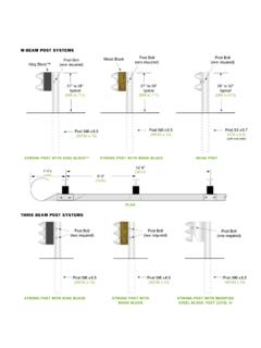
6 Posts maintain the rail at the proper mounting height, provide some lateral support to limit the deflection of the rail, yet bend to allow the vehicle to pass over the posts without snagging the vehicle. Corrugated Beam Guardrail differs in that it uses larger, stronger posts which reduce the guardrail deflection more than box beam, but would snag a vehicles wheels if it weren't for the block-outs mounted to the post thereby separating the rail and hence the vehicle's wheels from snagging on those strong posts. Figure 3 For side impacts, WY-BET performs like box-beam guardrail.
7 3. GRADING. Proper site grading is very important for all guardrail installations. The ground cross-slope from the roadway shoulder to the face of any guardrail should be 1:8. (rise to run) or flatter. This slope should extend a minimum of m (2 ft.) behind the guardrail. For projects which accommodate grading operations, this minimum distance behind the guardrail should extend to m (4 ft.) behind the guardrail at the nose of the terminal when possible. It is strongly recommended to smoothly flatten the slope to a 1:10 or flatter at the nose of the terminal.
8 A. traversable cross-slope, 1:3 or flatter (preferably 1:4 or flatter) should be provided behind the guardrail (starting at the slope break line) for all installations in which the guardrail terminates inside the clear zone. Relatively flat grading at guardrail and end terminals helps to prevent errant vehicles from striking these appurtenances either too high or too low. Figure 4A- Cross slope into the face of guardrail should be 1:8 (rise to run). or flatter. That slope should be flattened to a 10:1 or flatter at the nose of the terminal. Figure 4B- Preferred minimum slope treatment around the end terminal where grading operations permit this treatment.
9 The alignment should be set as shown in the project plans as established by the appropriate design methodology (which is beyond the scope of this guide ). Some WY-BET Terminals are specified to be tangent to the roadway while others are flared away from the roadway. If the WY-BET is flared, it should not be flared at a rate steeper that 1:15 with respect to the roadway. It is advised to slightly flare the terminal from the roadway, even on tangent installations if the slope grading requirements can still be met. This reduces the likelihood of a nuisance 4.
10 Impact, such as a snowplow clearing snow from the shoulder of the road. It is desirable to have the nose of the terminal set behind the line delineators when possible. Whether flared or not flared, the entire length of the WY-BET must be installed straight and true to allow it to properly telescope when needed. PRIOR TO installation . The following must be performed on each WY-BET prior to installation . Place the outer rail on the back of a flat bed or other suitable location. Slide the inner rail inside the outer rail for its full length using manual labor only.