Transcription of The Force Table - SMU Physics
1 1. The Force Table Introduction: "The Force Table " is a simple tool for demonstrating Newton's First Law and the vector nature of forces. This tool is based on the principle of equilibrium . An object is said to be in equilibrium when there is no net Force acting on it. An object with no net Force acting on it has no acceleration. By using simple weights, pulleys and strings placed around a circular Table , several forces can be applied to an object located in the center of the Table in such a way that the forces exactly cancel each other, leaving the object in equilibrium.
2 (The object will appear to be at rest.) We will use the Force Table and Newton's First Law to study the components of the Force vector. Theory: As we saw in the inclined-plane experiment, any vector can be decomposed into several other vectors which, when added together, produce the original vector. This was essential to our study of the inclined plane, where the Force we were concerned with was the component of the weight vector which was parallel to the inclined plane. Sometimes, when doing calculations which involve adding several vectors, it is useful to break up the individual vectors into components and then add the components.
3 How could this extra step actually facilitate the solution? Most vectors are given only by their magnitude and direction, with magnitude being some scalar positive number and direction given by some angle. If you are trying to add the vectors using a protractor and ruler by the "parallelogram method", you will have to draw all the vectors, then add them up graphically, one by one, until you have completed the task and with questionable precision in your result. The component method reduces the addition to one step. Furthermore, this step is analytical (adding numbers) rather than graphical (drawing pictures), yielding the best possible precision.
4 In the inclined-plane experiment, the down-hill Force was the component of the weight vector which was parallel to the plane. We found this component by multiplying the weight by the sine of the angle of the plane. Now let us consider a more general case. In the Cartesian coordinate system, a point on the graph is specified by two scalar numbers, x and y. The coordinate x gives the distance and direction along the x-axis, and the coordinate y gives the distance and direction along the y-axis, from the origin to get to the point in question.
5 The absolute value of the coordinate indicates the length along the 2. axis, while the sign (positive or negative) tells the direction (left or right, up or down) of motion. How can this be used with vectors? Consider the vector R which lies in the x-y plane. If we place the tail of R at the origin, R points away from the origin like the hand of a clock. R also makes some angle . with the positive x -axis (measured counter-clockwise). The tip of R rests on the Cartesian coordinate (Rx , Ry ). In fact, Rx and Ry are called the components of the vector R.
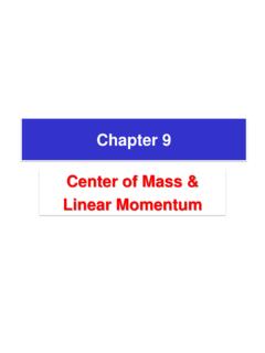
6 Now consider another vector S, its components, and the sum of R and S, the vector T. y Ry S. Ty R. T. S x Tx . x S Rx Sy R+S=T. Observe that the components of S are negative in this example. The components of the resultant vector T, (Tx , Ty ) are equal to (Rx + Sx , Ry + Sy ). Since the length of T is the hypotenuse of a right-triangle with sides of lengths Tx and Ty , the magnitude of T. is: T = Tx 2 + Ty 2. The convenient thing about the component method is that you only have to add scalar numbers to get the final vector.
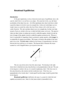
7 This really speeds things up when you have more than two vectors to add. But how do you get the components from the magnitude and the angle ? The Force Table gives you the angle and the magnitude of the different vectors. How can a vector as such be decomposed into x and y components ? Lets look at the right-triangle O-A-H (notation for opposite, adjacent, hypotenuse): 3. H. O.. A. O. As we saw last week, the sine of angle is the ratio H . There is another function A. called the cosine, which is the ratio H . Therefore, if you know and the length of side H, you can calculate O and A: O = H sin.
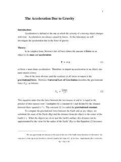
8 A = H cos . Now if we set the right triangle O-A-H in such a way that side A lies along the x- axis and side O lies along the y-axis, and treat side H as our vector R, we see a way to calculate the x and y components: y Ry R.. x Rx Rx = R cos . Ry = R sin . You will notice that for greater that 90 , the numbers Rx and Ry may be negative. For the Force Table , the components of the individual tensions will be calculated by this method. The x and y components of a Force T in the direction given by the angle . will be: Tx = Tcos.
9 Ty = Tsin . 4. The angle will always be measured as above, with zero pointing along the positive x-axis and increasing in a counter-clockwise direction. Procedure: Part One: 1. Level the Force Table and put one of the pulleys at the angle 0 . 2. Put the slot weights in the holders such that each one has a total mass of 200 g. 3. Arrange the other two pulleys such that the ring connecting the different strings remains fixed at the exact center of the Table . Tap the Table to make sure that it remains fixed. At this point the ring is at equilibrium.
10 4. Record as T1, T2 , and T3 , the tensions in each of the strings. 5. Record as 1 , 2 , and 3, the respective angular positions of the pulleys. 6. Find the x and y components of each of the tensions. Record these as T1x , T1y, et cetera. 7. Now find the resultant Force vector by adding the respective components of the individual string forces. What do you find? Part Two: Repeat part one, but change the mass on the pulley #1 at 0 to 300 g. Part Three: Repeat part one, but with masses of 200, 300, and 400 g. Conclusions: 1.