Transcription of The Magica Audio Fil - N5DUX
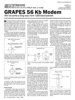
1 Lirn Pepper W6 QIF 44 El Carnino Moraga Orinda CA 94563 The Magica Audio Fil A variable-frequency notch filter plus a peaking circuit will do wonders for your reception. And this project will almost build itself. A udio filtering is a well- known process for improving receiver selectiv- ity and many articles have FO = I 27 ~4fi ALL RESISTORS 0 I% Fig. 1. Original circuit. been written on the subject. Because I have been in the process of building a direct- conversion receiver, I have been most interested in the subject. However, in order to further improve the re- ceiver, I wanted more than the usual passband type of filter. Since one of the re- ceiver modes is CW, I wanted a notch filter with a variable frequency and a variable-frequency peaking circuit. The notch filter could also be used on SSB reception to reject hetero- dynes from AM stations. Some of the requirements that I wanted for the notch filter were.
2 A high Q (so the band- width at the 3dB point of the notch frequency was approximately 200 Hz with a rejection of greater than 20 dB) *the capability of shifting the notch frequency from 500 to 3 kHz .a minimum number of parts. The Frequency-Notching Circuit Most articles I'd seen on this subject showed at least three or four operational amplifiers plus a multitude of resistors and capacitors and therefore did not satisfy my third requirement. One day, I accidentally ran across a number of cir- cuits in a National Semicon- ductor Linear Applications Manual.' The circuit that in- terested me the most was the one providing variable frequency-notching using a variable capacitor. This cir- cuit was constructed on a prota board and performed quite well, but the frequen- cy range was limited by the maximum value of the ca- pacitor. The basic circuit is shown in Fig.
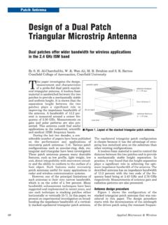
3 1. The major drawback of this circuit was the large physical size of the capacitor as compared with the rest of the circuit. Looking at the formula for the notch frequency (Fig. I), one can see that the fre- quency is a function of R4, C1, and C2. The frequency varies directly as R4 and by the square root of C1 and FREQUENCY I Hz1 I I FREQUENCY (Hz1 Fig. 3. Peaking circuit. Fig. 2. Notch circuit. 73 Magazine * November, 1983 C2. Thus, if the resistor is doubled in value, the fre- quency doubles. Doubling the capacitors only gives times the change. I decided to build the circuit with R4 variable and again results were very good. The fre- quency-range requirements were met and the rejection was greater than 20 dB. It did have one problem that was also experienced with the variable-capacitor cir- cuit. In order to achieve maximum rejection at the high end vs.)
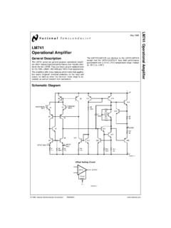
4 The low end, R3 had to be varied. Experi- menting further, I found that if R5 were varied and R3 and R4 were properly chosen, only one control was neces- sary. Almost equal rejection could then be achieved across the whole range. A typical response is shown in Fig. 2. The Peaking Circuit Since the above circuit was rather novel (there is no signal inversion from input to output at the off null point), I started to look at voltages at various points with an oscilloscope. To my amazement, I found that when the output was going to null on ICI, the output was peaking on IC2. Eureka!-Here was the sec- ond circuit I was looking for. To accomplish peaking, only IC2 was needed. This circuit was constructed and the results are shown in Fig. 3. R,, is necessary to prevent saturation of the amplifier. The gain of this stage is about 10-therefore the in- put must be less than volts.
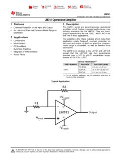
5 The power supply used was plus and minus 8 volts to be equivalent to the supply to be used in thefinal construction. It will be noticed that there is an additional resis- tor that can be switched in or out .in the final circuit. When the resistor is in, the peak is broadened and the circuit can be used on AM or SSB to modify the speech characteristics of the trans- PFIKING NOTCHIN% Audio IMPLINER !OK $'$ 22021 2,Fps~~~~~~ PHONES OR 0 22 DIODE BRIDGE 12345 ALL RESISTORS ,,$& 1/4 W 10% 2200pF IZVAC 51 SHOWN PEAKING IN $2 SHOWN IN CW POSITION +kqisEc Fig. 4. mitted signal being re- ceived. It can reduce the low frequencies and accen- tuate the frequencies that transmit the spectrum that contains the most intelli- gence. It also reduces higher frequencies, thereby reduc- ing background noise. Combination Notch and Peaking Circuit Fig. 4 shows the final cir- cuit combining the two cir- cuits.
6 The circuit was con- structed on a perfboard us- ing wire-wrap sockets. The perfboard is mounted in a Radio Shack box with I-inch spacers. Both the LM383 and the transformer are mounted to the box. One note of caution-the uF capacitor on the output to ground on the LM383 should be mounted on the device terminals. The input cable, the output jack, and the 115-V-ac input all come in on one end of the box and the potentiometers mount on top. For some reason, not many articles ever use perf- boards and wire-wrap sock- ets. PC boards should be used for rf work, but the perfboard does very well for Audio frequencies. The nice thing about wire-wrap cir- cuits is that if you make a mistake, it can be corrected or modified easily. The fol- lowing are some hints on building with a perfboard and wire-wrap sockets. Parts List Quantity Part R. S. part# 3 LM741 276-007 1 LM383 276-703 1 Phone plug 274-1 536 1 Phone jack 274-252 1 50k linear pot 271-1716 1 10k Audio taper pot 271-1723 1 5k linear pot 271-1714 2 470-pF capacitors 272-125 3 1.
7 O-uF capacitors 272-996 2 100-uF capacitors 272-1016 2 capacitors, 272-1 070 1 2200-uF capacitor 272-1020 1 12-V-ac transformer 273-1 505 3 8-pin DIP w-w sockets 276-1988 1 SPST switch pwr 275-602 2 SPST switches 271-612 1 Chassis box 270-238 1 Line cord 278-1255 3 Knobs Your choice 1 Perf board 276-1 395 1 pkg Push-in terminals 270-1392 1 Wire-wrap tool 276-1570 3 10k '14-W resistors 2 'A-W resistors 1 56k %-W resistor 1 47k 'A-W resistor 1 '/4-W resistor 2 1 k l/4-W resistors 1 220-Ohm '14-W resistor 1 '/4-W resistor 1 Bridge rectifier 276-1151 Wire-wrap wire Your choice of colors Misc. hardware 1. Make a Xeroxa copy of the IC sockets. Remember the schematic; every time that the numbering on the you put in a wire, mark it wire side is opposite to that down. This is especially help- on top. ful should you put the proj- 3. 1 use model-airplane ect away and come back to cement to hold the IC sock- it later.
8 Ets in place. If you want to 2. Using a marking pen on reuse the perfboard, this the wire side of the board, type of glue allows the sock- indicate which pin is #I for et to be easily removed. 73 Magazine e November, 1983 15 <% 43- SPEECH SYNTHESIS, Call or write for detailed -%- --=pig?- advanced specifications on the RC-8s iPi , $ computer Repeater Control Board. -&! ?RL~'& controls, inc. 1081 6 Northr~dge Square a Cupertino, CA 95014 (408) 749-8330 ~124 Clean the board with ace- tone when the sockets are removed. 4. It is also helpful to use different colors of wire for different parts of the cir- cuitry. 5. Push-in teminals (Radio Shack #270-1392) are used to mount the resistors and capacitors. The wire-wrap wires are soldered to these terminals on the wire side of the board. (A special tool is available to insert these ter- minals but is not available from Radio Shack.)
9 Long- nose pliers can be used but are nowhere near as satis- factory as the tool.) 6. Mount the components when the push-in termi- nals are in place so as not to lose track of which ter- minal goes with which component. Fig. 5. Another application for peaking-circuit decoder. 7. Wire-wrapping is done with a manual tool to conve- niently allow interchanging of wire colors. If you have never used a wire-wrap tool, the operation is very simple. In learning, the best way is to measure the distance be- tween the two points to be wired and add 1 l/i inch if wire-wrap to wire-wrap, add 718 inch for wire-wrap to teminal, and add 'A inch for terminal to terminal. For good measure, add on about '/2 inch so the wire will not be too tight. Strip both ends 518 inch for wire-wrapping and inch for terminals. Stripping is done with a special tool provided with the wire-wrap tool. The bare wire is inserted into the end of the wire-wrap tool with the wire entering the sniall- est hole on the end of the tool.
10 Place the tool over the terminal post to be wrapped and rotate the tool in a clockwise direction for about ten turns. The connec- tion is now made. If you make a mistake, a tool is available to rotate in the op- posite direction to remove the wire. Circuit Operation When the project is fin- ished, the in~ut cable can be plugged inti the phone jack of any receiver and the out- put to either a speaker or headphones. Set 51, the peaking-circuit switch, to OUT. Tune in a CW signal and adjust the signal fre- quency to give about an 800-Hz tone. Throw S1 to IN and turn the peaking control to a point where the max- imum Audio is heard. The first thing you will notice with the peaking switch in is the reduction in noise. As you approach the peaking point, the signal will in- crease greatly in volume. Of course, if some other fre- quency suits you better than 800 Hz, that is the listener's choice.