Transcription of The New version of the German torque calibration …
1 IMEKO 20th TC3, 3rd TC16 and 1st TC22 International Conference Cultivating metrological knowledge 27th to 30th November, 2007. Merida, Mexico. The New version of the German torque calibration standard DIN 51309:2005-12 a comparative overview D. R ske Physikalisch-Technische Bundesanstalt (PTB, Germany) Email: Abstract In December 2005, the new version of the DIN 51309 was issued by DIN, the German Institute for Standardization. This standard takes into account some fundamental ideas about the target application of a torque transducer, for example high-level inter-comparison measurements or measurements in industrial environments. Two cases are considered and two different calibration results are calculated on the basis of a standard calibration procedure. For some inter-comparisons, the hysteresis of the transducer does not have any influence on the result and is therefore excluded.
2 This paper shows, on the one hand, the new version in comparison with other standards (e. g. EA-10/14) and some guidelines of the DKD, the German calibration Service, and describes, on the other hand, its application to torque reference machines. Keywords: torque , calibration standard, DIN51309, hysteresis, torque reference machine 1 Introduction The calibration procedure of a measuring instrument should meet the requirements of the device s future application as accurately as possible, and a suitable calibration result should be calculated on this basis. On the other hand, calibrations should be carried out according to existing standards or guidelines for the calibration . One of the well-established calibration standards for static torque measuring devices is the DIN 51309 [1]. Nevertheless, there had been some weaknesses in the former version of this standard regarding mainly the uncertainty calculations and the conformity to the Guide to the Expression of Uncertainty in Measurement (GUM).
3 The revision of this standard in the years 2004 and 2005 offered the possibility for some improvements. These will be explained later on in this paper. DIN 51309 : 1998-02 In the past, according to the former version of the standard [2], there was only one calibration result: The calibration result Xr shall be calculated according to equation (1*) as the mean value of the indicated results obtained from the increasing series in the changed rotated mounting positions. = =njjjIInX1 ,0r1 (1*) where n number of increasing series in different mounting positions. The results measured in the 0 position in the second series at increasing torques (classes to ) are not included in the calculation of Xr . 0,jjII is the zero-reduced indication of the transducer at the given load step in mounting position j. The hysteresis h, caused among other things by creep in the material of the transducer s elastic body and the strain gauge application, is considered as a random variable as well as the deviation associated with the interpolation (fa): The relative uncertainty of measurement is calculated according to equation ( ) for each calibration stage.
4 22K2a22202MG6112124181121121hMrfbbfu+ +++ += . ( *) In ( *), the following designations are used: b - relative repeatability error in different mounting positions b - relative repeatability error in unchanged mounting position f0 - relative error of the residual zero signal r - resolution of the indicating device MK - the applied calibration torque . In the case of reduced calibrations for the classes 1, 2 or 5, instead of measuring b , the contribution of b (281b) will be taken into account a second time. It is known that the hysteresis is a systematic deviation and not a random one, therefore ( *) is not correct. The same applies to the deviation from the linear fitting curve. Hence, (1*) is not suitable for applications where increasing and decreasing torque values are measured. Last but not least, there was no mathematical model given as a basis for an uncertainty calculation in conformance with the GUM.
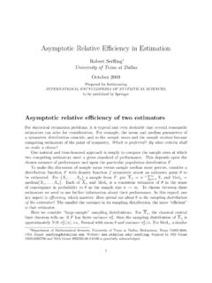
5 THE NEW DIN 51309 calibration results The new version of the DIN 51309 [1] takes this into account. First of all, the most obvious modification is the calculation of two different results (see figure 1) one for measurements with increasing torque value only (case I) and one for increasing and decreasing torque amplitudes (case II). In the first case, the result Y given by ( )( )() = =njjjIMInMY1,0KK1 (1) is the same as in (1*) before. But the hysteresis is completely ignored and does not contribute to the uncertainty of measurement, thus improving the result by reducing the uncertainty. This case is applicable to high-precision measurements, for example in comparisons of torque standard machines with lever-mass-systems and air bearings - but also to measurements with increasing torque only, for example the measurement of the increasing tightening moment of a screw connection.
6 In the second case, the result Yh is given by ( )()() = +=njjjjIMIMInMY1,0 KKKh21, (2) i. e. the mean over the different mounting positions of the mean value of the indications at increasing Ij and decreasing I j torques reduced by the zero indication I0,j prior to the measurement series. The subscripted h indicates that the hysteresis will be taken into account here (see below). In conformity with the GUM, the symbol Y is used for the result, thus emphasizing that it is an output quantity of the calibration . The input quantities are now denoted by X. Figure 1: Results of a calibration according to DIN 51309 (synthetic data screenshot from a calibration certificate) Regressions The old version of the DIN standard required fitting curves (somewhat improperly called interpolation functions ) of 1st, 2nd and 3rd degree without absolute term (only 1st degree for classes 1 to 5).
7 A large number of calibration certificates produced at PTB showed that the approximation of the measurement results with a linear and a cubic function is sufficient. There is no need for an additional quadratic regression. Furthermore, from the application s point of view there is often the possibility to adjust the sensitivity using a linear scaling factor and a linear regression. When a PC is used, the fitting curve can be of any degree, but the cubic function is adequate. Therefore the calculation of a 2nd degree function was omitted. Furthermore, the calculation of the 3rd degree function is now necessary only for case I assuming that a higher precision requires a higher degree of approximation. The result calculated for case II according to (2), thus averaging the hysteresis for increasing and decreasing torque nearly to zero, is very often quite linear.
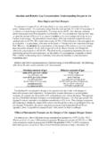
8 In addition, the non-linearity of the result (2) is normally much smaller than the effect of the hysteresis. Therefore only a linear regression is applied. Figure 2: Fitting functions of a calibration according to DIN 51309 (synthetic data - screenshot from a calibration certificate), (Footnote: The linear interpolation equation for clockwise torque and anticlockwise torque cannot be used as a calibration result for alternating torque . It can only be used to adjust the indicator optimally for clockwise torque and anticlockwise torque with a single calibration factor.) Uncertainties Another major difference between the two issues of the standard is the definition of the parameters for the uncertainty contribution: - reproducibility b - repeatability b - residual zero deviation f0 - hysteresis h - deviation from fitting curve fa - deviation of the indication for transducers with defined scale fq.
9 All these parameters are now calculated in absolute terms, in indicated units and not in %. Their relative values must be calculated for the classification. This means that, in general, there will be different classifications for cases I and II. Instead of ( *) there are now different possibilities to calculate an uncertainty (with the same minor change for transducers of class 1, 2 or 5 as before). 1. Case I, Cubic Regression In this case the relative expanded (k = 2) uncertainty of measurement is calculated according to ( )( )( ) ( ) ( ) ( )( )K2E20K2'K2K2K2 KEK22 MwMwMwMwMwMwMWfabbr++++ + = (3) with uncertainty contributions from Table 1. The factor 2 near ()K2 Mwr takes into account that a measurement value is calculated as the difference between the reading at calibration torque and the reading at zero, thus containing the influence of the resolution r twice.
10 The residual zero deviation f0 reflects some influence of the creep (see below), but it can be neglected in most of the cases. 2. Case I, Linear Regression Due to the systematic nature of the deviation fa from the linear fitting curve, the relative expanded (k = 2) uncertainty of measurement is calculated according to ( )( )( ) ( ) ( ) ( )2 KKaE20K2'K2K2K2 KEK%100)()(22 ++++ + =MYMfMwMwMwMwMwMWbbr (4) with the uncertainty contributions from Table 1. 3. Case II, linear regression Due to the systematic nature of the hysteresis h and the deviation fa from the linear fitting curve, an uncertainty interval is calculated according to ( )()( )()( )( )( ) ( ) ( ) ( )E20K2'K2K2K2 KEKhKKhKaK22%1002%100'MwMwMwMwMwMYMhMYMf MWbbr+++ + ++ + = (5) with the uncertainty contributions from Table 1, but now related to Yh(MK).