Transcription of Lab Test Procedure for Determining Stated …
1 Revised 10/10 PTI LAB TEST Procedure FOR Determining Stated relative TORQUE MEASUREMENT FOR CORDED AND CORDLESS DRILLS, DRILL/DRIVERS, AND SCREWDRIVERS PURPOSE The purpose of this document is to define a common method for measuring a relative output torque. SCOPE This Procedure applies to all corded and cordless drills, drill/drivers, and screwdrivers not intended for assembly/production use. It does not apply to products employing impacting devices such as hammer drills, rotary hammers and impact drivers. The relative Torque Measurement (RTM) determined in accordance with this document represents the output torque developed by the product under test with a 95% confidence.
2 The RTM is obtained under laboratory test conditions and is intended for use in comparing similar products. The actual output torque generated by an individual sample may vary slightly. The RTM should not be interpreted as a statement of the product s performance when used for precision fastening operations or in applications where tightening is specified. GENERAL CONDITIONS FOR THE tests tests according to this Procedure are type tests . The test is made on a total of five normal production samples which have not been modified. The test consists of five trials on each sample. Additional samples shall be used for testing at different supply voltages.
3 Revised 10/10 Tools provided with controls or switching devices are tested with these controls or devices adjusted to their setting which generates the highest torque. If the adjusting means of the control is accessible without the aid of a tool, this subclause applies whether the setting can be altered by hand or with the aid of a tool. If the adjusting means is not accessible without the aid of a tool, and if the setting is not intended to be altered by the user, this subclause does not apply.
4 The tests are made in a draught-free location and at an ambient temperature of 20 ( 5) C. Tools having more than one rated voltage are tested for all rated voltages. The RTM for a tool tested at a specific voltage only applies to that tool/voltage unless otherwise confirmed by testing. For cordless tools, all testing shall be performed with conditioned battery packs. Conditioning shall consist of five charges and five discharges for each battery pack sample used during testing. Charging shall be performed with the appropriate charger recommended by the manufacturer for the battery pack under test, or a suitable device capable of duplicating the charger function.
5 For Ni-Cd and Ni-Mh, discharging shall consist of a 2c discharge rate to .9 volts per cell. For Li-ion, discharging should consist of a 2c discharge rate or as recommended by the cell manufacturer to volts per cell. Using a previously conditioned battery pack, from , the battery pack is to be charged, allowed to cool to room temperature and then discharged for a period of 4 minutes with a resistive load determined as follows: V/ (5C) ohm (where V is the voltage of the battery Stated by the manufacturer and c is the manufacturer s Stated ampere-hour rating of the battery pack. Allow the sample to return to room temperature prior to testing. Unless otherwise specified, a battery pack as prepared in accordance with and shall be used for each cordless tool test.)
6 For corded tools, all testing shall be performed with a regulated power supply circuit which provides the nominal voltage and frequency provided on the tool s nameplate ( 120 volts ac 60 Hz). The power supply circuit shall also be suitably sized to withstand the stall current of the unit under test. For corded tools, all relevant normally-supplied motor and electric power supply components such as the power cord, switch, speed controls, etc. shall be in the circuit, so that normal power losses in the tool are reflected by the measurement. Procedure Setup Revised 10/10 The test sample shall be supported to prevent tool movement due to reactionary torque.
7 In addition the tool shall be supported so that it can be fed inward toward the rundown adapter. This will insure that the operator does not absorb the energy from the sample during testing. See Section 5 for a typical test fixture. If the test sample has an adjustable clutch, the clutch should be set in the full-lock position. If the tool clutch slips during testing, the results are considered to be invalid. If the tool is equipped with various gear ranges, set the tool to the gear range which results in the greatest torque value. If the test sample has forward and reverse rotation, set the rotation in the forward position. Torque shall always be measured in the forward position.
8 Either a cordless tool having a battery pack that is prepared in accordance with , or a corded tool connected to a power supply circuit in accordance with , shall be mounted on the fixture. The test sample shall now be connected to a model 10002-I-ETT (electronic torque tester) manufactured by CDI Torque Products. In addition, a joint rate simulator adaptor shall be placed between the output of the test sample and the torque tester. The lowest capacity joint rate simulator shall be used which will measure the expected maximum output torque of the tool. CDI Torque Products offers the following three sizes to choose from: Model 900-0-KIT capacity 50 in.
9 Lbs. Model 900-2-01 KIT capacity 400 in. lbs. Model 900-3-01 KIT capacity 1000 in. lbs. Testing Manually energize the test sample as quickly as possible by actuating the switch to the full on position. This action should represent normal use. Allow the joint rate simulator to tighten until it comes to a complete stop. Record the output torque. Allow the test sample to cool a minimum of three minutes before performing the next trial. This will allow the test sample to cool prior to the next measurement, and insure more consistent readings. Repeat steps and for a total of five trials. For cordless tools, utilize the same battery pack or sample for the five trials without recharging.
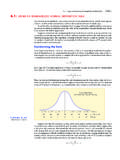
10 Repeat steps through on four additional samples. Revised 10/10 Calculations Background: The following statistical analysis of the recorded data serves as a method to determine the RTM of the tool with a 95% confidence. Once all twenty-five trials have been completed, the average torque value of the trials, the standard deviation for the trials, and the high and low data point limits shall be calculated by following the equations: Average Torque, Tavg = (Ti)/n Sample standard deviation calculated by s=sqrt ( (Ti-Tavg)2/(n-1)) High data point limit = Tavg+ (2*s) Low data point limit = Tavg-(2*s) Where.