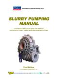
Transcription of The Sizing & Selection of Hydrocyclones
1 THE Sizing AND Selection OFHYDROCYCLONESBy Richard A. Arterburn For many years, Hydrocyclones ,commonly referred to as cyclones, havebeen extensively utilized in the classificationof particles in comminution circuits. Thepractical range of classification for cyclonesis 40 microns to 400 microns, with someremote applications as fine as 5 microns oras coarse as 1000 microns. Cyclones areused in both primary and secondary grindingcircuits as well as regrind circuits. Theinformation given in this paper is intended toprovide a method, at least for estimatingpurposes, of selecting the proper numberand size of cyclones and to determine theproper level of operating , it is recommended that cyclonesuppliers be consulted for sizingconfirmation.
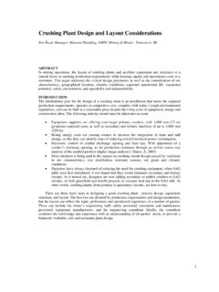
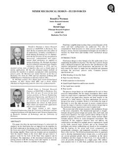
2 Some cyclone suppliersemploy digital computers to aid in the sizingand Selection of DESCRIPTION AND BASICOPERATION Figure 1 shows a cutaway view of atypical cyclone . During operation, the feedslurry enters the cyclone under pressurethrough the feed pipe into the top of thecylindrical feed chamber. This tangentialentrance is accomplished by two types ofdesign, as shown in Figure 2. Since themajority of research has been done with theinvoluted type, the graphs and relationshipsshown may not be strictly applicable to the feed enters the chamber, a rotation ofthe slurry inside of the cyclone begins,causing centrifugal forces to accelerate themovement of the particles towards the outerwall.
3 The particles migrate downward in aspiral pattern through the cylindrical sectionand into the conical section. At this point thesmaller mass particles migrate toward thecenter and spiral upward and out throughthe vortex finder, discharging through theoverflow pipe. This product, which containsthe finer particles and the majority of thewater, is termed the overflow and should bedischarged at or near atmospheric pressure. The higher mass particles remain in adownward spiral path along the walls of theconical section and gradually exit throughthe apex orifice.
4 This product is termed theunderflow and also should be discharged ator near atmospheric PARAMETERS FOR STANDARDCYCLONE The definition of a standard cyclone isthat cyclone which has the propergeometrical relationship between thecyclone diameter, inlet area, vortex finder,apex orifice, and sufficient length providingretention time to properly classify with the involuted type design , thegraphs and mathematical relationshipsshown for proper Selection and Sizing ofcyclones apply to the standard cyclone geometry. The main parameter is the cyclonediameter.
5 This is the inside diameter of thecylindrical feed chamber. The next parameter is the area of theinlet nozzle at the point of entry into the feedchamber. This is normally a rectangularorifice, with the larger dimension parallel tothe cyclone axis. The basic area of the inletnozzle approximates times the cyclonediameter squared. The next important parameter is thevortex finder. The primary function of thevortex finder is to control both the separationand the flow leaving the cyclone . Also, thevortex finder is sufficiently extended belowthe feed entrance to prevent short circuitingof material directly into the overflow.
6 Thesize of the vortex finder equals timesthe cyclone diameter. The cylindrical section is the next basicpart of the cyclone and is located betweenthe feed chamber and the conical section. Itis the same diameter as the feed chamberand its function is to lengthen the cycloneand increase the retention time. For thebasic cyclone , its length should be 100% ofthe cyclone diameter. The next section is the conical section,typically referred to as the cone included angle of the cone section isnormally between 10O and 20O and, similarto the cylinder section, provides The termination of the cone sectionIs the apex orifice and the critical dimensionis the inside diameter at the discharge size of this orifice is determined by theapplication involved and must be largeenough to permit the solids that have beenclassified to underflow to exit the cyclonewithout plugging.
7 The normal minimumorifice size would be 10% of the cyclonediameter and can be as large as 35%.Below the apex is normally a splash skirt tohelp contain the underflow In determining the proper size andnumber of cyclones required for a givenapplication, two main objectives must beconsidered. The first is the classification orseparation that is required, and the secondis the volume of feed slurry to be determining whether these objectivescan be achieved, it is necessary to establisha base condition as follows:1. Feed liquid water at 20O Feed solids spherical particlesof sp Feed concentration less than1% solids by volume4.
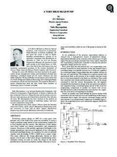
8 Pressure drop 69 kPa (10psi).5. cyclone geometry standardcyclone as described aboveCLASSIFICATION Historically, classification has beendefined as the particle size of which 1% to3% reports to the cyclone overflow withcoarser particles reporting to the cycloneunderflow. Recent investigations havedefined classification as the particle size ofwhich 50% reports to the overflow and 50%to the underflow, or the so-called D50C 3 shows the typical relationshipbetween particle diameter and the percentrecovered to underflow.
9 The portion of thecurve near the 50% recovery level is quitesteep and lends itself readily to determiningan accurate particle diameter. Examinationof the recovery curve near the 97% to 99%recovery level shows that the curve is nearlyhorizontal and a small differential couldchange the micron diameter considerably. [Note: The particle size shown on Figure3 and also used for calculations in this paperis defined as the minimum particle diameterof a given size band. For example, aparticle that passes a 150 mesh screen (105microns) but is retained on a 200 meshscreen (74 microns) would actually have adiameter between 74 microns and 105microns.]
10 For this paper, the size of 74microns would be used for particles in thissize range.] Figure 3 also shows that the actualrecovery curve does not decrease below acertain level. This indicates that a certainamount of material is always recovered tothe underflow and bypasses classification. Ifa comparison is made between theminimum recovery level of solids to theliquid that is recovered, they are found to beequal. Therefore it is assumed that apercent of all size fractions reports directly tothe underflow as bypassed solids in equalproportion to the liquid split.