Transcription of The SysML notation - UMD
1 Chapter 5 The SysML notationWords are but symbols for the relationsof things to one another and to us;nowhere do they touch upon absolute Nietzsche (1844 1900) IntroductionThis chapter describes the nine SysML diagrams. Following this introduction, theterminology used throughout the chapter is explained and the structure of SysMLdiagrams is discussed. This is followed by a discussion ofstereotypesand then ofthe SysML meta-model, which forms the basis of this chapter. Following this, eachof the nine diagrams is described in turn. For each diagram type there is a briefintroduction, a discussion of the diagram elements through its meta-model andnotation, examples of how to use the diagram and a Diagram orderingSo far, we have looked at two of the diagrams in some detail whenblock definitiondiagramsandstate machine diagramswere used to illustrate structural andbehavioural modelling in Chapter 4; these diagrams are shown again in this chapterfor the sake of completeness and also to introduce the meta-model using diagramsthat are already well chapter first covers thestructural diagramsand then thebehaviouraldiagrams.
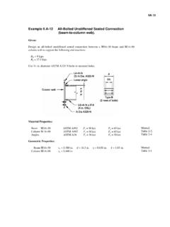
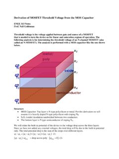
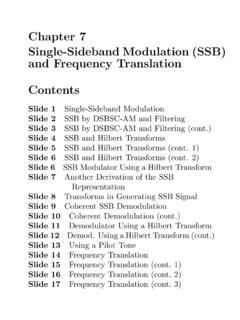
2 Within these groupings there is no significance in the ordering of thediagrams. They are simply presented in, what is from the author s point of view, alogical order. Therefore, the various parts of this chapter may be read in any The worked exampleWhen discussing each of the SysML diagrams in the sections that follow, they will bediscussed using an example System taken from the world of escapology. The Systemconsists of an escapologist who is placed in a rectangular coffin, which is then placedinto a hole. Concrete is pumped into the hole, under computer control, until the holeis full. The escapologist has to escape from the coffin and the concrete-filled holebefore his breath runs out.
3 Figure shows the set-up for the escape. Holt, Jon; Perry, Simon, Jan 01, 1753, SysML for Systems Engineering. 2nd Edition : A Model-Based ApproachThe Institution of Engineering and Technology, Stevenage, ISBN: 9781849196529 This is a classic escapology stunt that has been performed by many people. It isalso a dangerous one, and escapologists have lost their lives performing it becausethe System Requirements and constraints were not properly understood orevaluated. One such performer was Joe Burrus who died 30 October 1990 whenthe weight of the concrete crushed the coffin he was in. This example is asocio-technical System that includes hardware, software, People and Process.
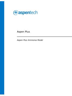
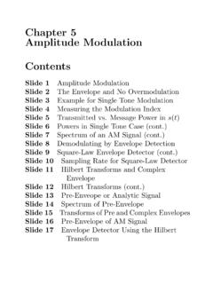
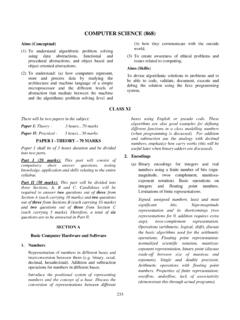
4 Itlends itself readily to the use of all of the SysML diagrams. What is more, it is notan example based around a library, an ATM or a petrol pump. The literature isalready too full of such The structure of SysML diagramsEach diagram in the SysML has the same underlying structure, which is intended toprovide a similar appearance for each, as well as making cross-referencing betweendiagrams simpler. The structure of each diagram is shown in Figure diagram in Figure shows that each diagram is made up of one ormore graphic node and one or more graphic path . Each graphic path relatestogether one or two graphic node.
5 Examples of graphic nodes includeblocksonblock definition diagramsandstatesonstate machine diagrams. Examples ofgraphic paths include:relationshipsonblock definition diagramsandcontrol flowsonactivity text stereotype on theblocksis an example of .. a mechanism by which the SysML can be extended. Indeed, thePumpConcreteHoleCoffinEscapologiststa rtstopreversePumpControllerFigure The coffin escape stunt122 SysML for systems engineering Holt, Jon; Perry, Simon, Jan 01, 1753, SysML for Systems Engineering. 2nd Edition : A Model-Based ApproachThe Institution of Engineering and Technology, Stevenage, ISBN: 9781849196529 SysML itself is defined usingstereotypeson the underlying unified modellinglanguage (UML).
6 Stereotypesare discussed in Section FramesAny SysML diagram must have a graphic node known as aframethat encapsulatesthe diagram in order to make identification of, and navigation between, a defined format. This format, along with other guidelines forthe use offrames, is described in detail in Chapter 6. Examples offrameswill beseen around all the diagrams in the Examples subsections for each of the SysMLdiagrams in the following StereotypesStereotypesprovide a way to extend the SysML . They represent a powerful way todefine new SysML elements by tailoring the SysML to your order to usestereotypeseffectively, it is first necessary to be able to spot onewithin a model.
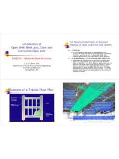
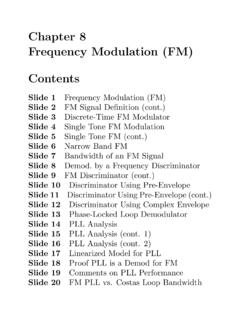
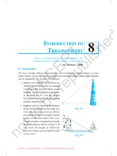
7 Visually, this is very simple, asstereotypesare indicated byenclosing the name of thestereotypewithin a set of double chevrons. Indeed, theSysML block itself contains the block shows two examplestereotypes: testCase applied to ablock(here representing a Scenario) and validate applied to * stereotype diagram stereotype graphic node stereotype graphic * togetherFigure Structure of each SysML diagramMinimise risk toescapologist testCase [Package] Scenarios [Failed Stunt Emergency] validate Figure Example stereotypesThe SysML notation123 Holt, Jon; Perry, Simon, Jan 01, 1753, SysML for Systems Engineering.
8 2nd Edition : A Model-Based ApproachThe Institution of Engineering and Technology, Stevenage, ISBN: 9781849196529 Adependency, represented by a dashed line with an open arrowhead, can beconsidered to be the weakest of the SysML relationships since it simply shows thatthere is some kind of (usually) unspecified relationship between the connecteddiagram not named and cannot have anymultiplicitiesassociated with them. SysML makes use of a number of stereotypeddependencies,particularly in therequirement diagramanduse case diagram, as described inSections and In Figure , a newstereotypeis used, one not found inthe standard SysML , in order to show that atest casevalidates ause case.
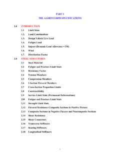
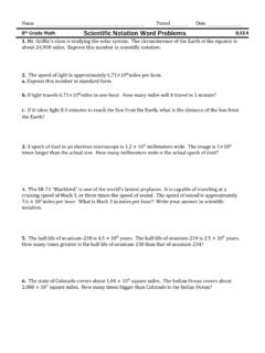
9 Note that testCase is a SysML stereotype and that the camel case naming is part ofthe be defined for any of the standard SysML elements. Unfortu-nately, the method by whichstereotypesare defined varies from SysML tool totool. However, a common diagrammatic method of defining astereotype, found inmany tools, is shown in Figure diagram in Figure shows the definition of the validate diagram shows twoblocks, Dependency and validate , which are relatedtogether by a special type ofspecialization/generalizationknown as used specifically when graphically by a filled-in triangle very similar to newstereotypeto be defined, in this case validate , is shown in ablock,which is itself stereotyped stereotype.
10 The SysML element that is being stereo-typed, in this case adependency, is shown in ablockcontaining the metaclass stereotype. The twoblocksare then connected with anextensionrelationship. Thisshows that the validate stereotypecan be applied to adependencyand, as definedin Figure , only adependency. In addition to the graphical definition, it is con-sidered good modelling practice to provide a textual description of thestereotypethat describes its intended use. metaclass Dependency stereotype validateFigure Defining a stereotype124 SysML for systems engineering Holt, Jon; Perry, Simon, Jan 01, 1753, SysML for Systems Engineering.