Transcription of The Touran Electrical system - VolksPage.Net
1 The TouranElectrical systemDesign and functionSelf-study programme ImportantNoteThis self-study programme explains the design and function of new contents will not be the latest testing, setting and repair instructions, please refer to the relevant workshop networking technology, used until now only in luxury class vehicles, will be a feature in com-pact vans, such as the Volkswagen control units installed in this system also manage tasks that were previously carried out by relays and switches. In order that these tasks can be fulfilled efficiently, the units have to exchange a great deal of information (data) between each other.
2 Such a high rate of data transfer would only be possible with a large number of cables if standard means were used, such as wiring con-nections. To keep the number of wiring connections at a manageable level, Volkswagen favours the use of data bus connections on a wider self-study programme is designed to help you better understand the networking concept of the Volkswagen Touran . It covers the allocation of control units to the various data bus systems, the fitting locations of relay slots, fuses and control units. Furthermore, it describes the various functions of and changes to the diagnosis.
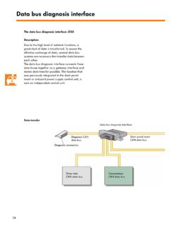
3 4 LIN data bus .. 16 Onboard power supply .. 20 Data bus diagnosis interface .. 24 Onboard power supply control unit .. 28 Windscreen wiper system .. 38 Rear window wiper system .. 44 Dash panel insert .. 46 Immobiliser .. 50 Convenience and infotainment settings .. 54 Lighting .. 55 Service .. 56Te st yo u r se l f .. 584 IntroductionFitting locationsThe onboard power supply of the Touran is decentralised. For this reason, the fuse boxes and relay slots are installed at various locations in the vehicle. The adjacent diagram shows the various fitting boxes and relay slots in vehicle's Electrical systemBack-up fuse box on leftin engine compartment Electrics box on left in engine compartment 5 Fuse box on left under dash panelS307_001 Relay carrier on onboard power supply control unit on left under dash panelRelay carrier on left under dash panel6 The networking conceptOverview of networked control unitsIn order that data can be transferred between the control units, these are networked via various data bus data bus diagnosis interface J533 (gateway)
4 Provides the interface for the data buses:-Drive train CAN data bus-Convenience CAN data bus-Infotainment CAN data bus-Dash panel insert CAN data bus-Diagnosis CAN data busIntroductionS307_049 LIN data busDrive train CAN data busConvenience CAN data busInfotainment CAN data busCAN data bus lineCommuni-cations lineLIN data bus lineDash panel insert CAN data busDiagnosis CAN data busIn addition to the CAN data bus, a number of electric components are networked via the LIN data data protocols have been chan-ged. Therefore, these control units cannot be exchanged with those of other vehicle models Touareg or RJ412J525J162R78J533T16J220J519J345J255J 136J285J431J388J604 CAN data busSensor7 KeyE221 Operating unit in steering wheelG85 Steering angle senderG273 Interior monitoring sensorG384 Vehicle inclination sensorG419 ESP sensor unitH8 Anti-theft alarm signal hornJ104 ABS with EDL control unitJ136 Seat adjustment control unitJ162 Heating control unitJ217 Autom.
5 Gearbox control unitJ220 Motronic control unitJ234 Airbag control unitJ255 Climatronic control unitJ285 Control unit with display in dash panel insertJ345 Trailer detector control unitJ386 Door control unit, driver sideJ387 Door control unit, front passenger sideJ388 Door control unit, rear leftJ389 Door control unit, rear rightJ393 Convenience system central control unitJ400 Wiper motor control unitJ412 Cellphone electronics control unitJ431 Headlight range control, control unitJ446 Parking aid control unitJ500 Power steering control unitJ503 Control unit with display for radio andnavigationJ519 Onboard power supply control unitJ525 Digital sound package control unitJ527 Steering column electronics control unitJ533 data bus diagnosis interfaceJ584 Wiper motor control unit front passenger sideJ587 Selector lever sensors control unitJ604 Auxiliary air heater control unitRRadioR78TV tunerT16 Diagnosis connectionJ217J104J234G85J446G419J527J38 6J393J387J389G273H8G384E221J500J587J400J 584S307_0028 Control units and fitting locationsThe
6 Adjacent diagram shows the controlunits that belong to the drive train CAN data bus and associated fitting data is transferred at a speed of 500 kbit/s. Transfer is made via the orange/black CAN high line and orange/brown CAN low line. To m ake data transfer more efficient,the CAN lines are units in drive train CAN data busMotronic control unit J220under plenum chamber coverABS with EDL control unit J104under bulkhead inengine compartmentAirbag control unit J234under centre console9S307_003 Control unit for headlight range control J431on left under dash panel,on tunnel supportdata bus diagnosis interface J533under dash panel.
7 Above relay carrierAutomatic gearbox control unit J217in wheel housing10 Control units and fitting locationsShown in the diagram are the control units of the convenience CAN data bus and their fit-ting speed of data transfer is 100 kbit/s. The data is transferred via the orange/green CAN high line and orange/brown CAN low line. Both CAN lines are entwined control unit J255in centre consoleConvenience system central control unit J393on right under dash panel, near centre consoleSteering column electronics control unit J527on steering column switchThe control units in the drive train CAN data bus11S307_004data bus diagnosis interface J533under dash panel, above relay carrierOnboard power supply control unit J519under dash panel, on relay carrierDoor control units J386, J387, J388.
8 J389in doorsTra i le r detector control unit J345in rear right side partParking aid control unit J446in rear right side part12 Control units and fitting locationsThe control units of the CAN data bus and fitting locations are shown in the adjacent infotainment CAN data bus transfers data at a rate of 100 kbit/s. The CAN high line is orange/purple and the CAN low line is orange/brown. Both CAN lines are entwined control units in the infotainment CAN data busCellphone operating electronicscontrol unit J412on front right in footwellHeater control unit J162on front right under wing13S307_005 Control unit with display for radio and navigation J503or Radio Rin centre console14 Dash panel insert CAN data busThe data bus transfers data from thedash panel insert to the data bus diagnosis inter-face.
9 The control unit with display unit in the dash panel insert and the data bus diagnosis interface are the only control units attached to this data CAN data busData transfer between the diagnosis connection T16 and the data bus diagnosis interface is via the diagnosis CAN data bus. Rate of data transferThe rate at which data is transferred is 500 kbit/s for both CAN data buses. IntroductionThe control units in the dash panel insert CAN data bus and in the diagnosis CAN data busControl unit with display unit in dash panel J285 The dash panel insert CAN data bus and the diagnosis CAN data bus are new data bus connections in the Volkswagen bus diagnosis interface J533under dash panel, above relay carrierT16 Diagnosis connectionon left in footwell16 The LIN data bus as sub data bus systemGeneral descriptionA sub data bus system connects control units with their Electrical components.
10 Among these com-ponents are, for example, control units, switches, sensors, actuators etc. This type of connection and data transfer is used in the Volkswagen Tou-ran for a number of systems. As a sub data bus system , the LIN data bus has an advantage in designation LIN stands for local interconnect network, and it means that all the associated Electrical components are within a set and limited area of the vehicle. It is possible for a number of LIN data bus systems to be installed in a vehicle. They will each have different functions to perform. A LIN data bus system consists of a master con-trol unit and one or more slave control units.