Transcription of THEORY, CONSTRUCTION, AND OPERATION
1 PART ITHEORY, CONSTRUCTION, AND OPERATION1 CHAPTER 1 PRINCIPLES OF OPERATIONOF SYNCHRONOUS MACHINESThe synchronous electrical generator (also calledalternator) belongs to thefamily of electric rotating machines. Other members of the family are the direct- current (dc) motor or generator, the induction motor or generator, and a numberof derivatives of all these three. What is common to all the members of this fam-ily is that the basic physical process involved in their OPERATION is the conversionof electromagnetic energy to mechanical energy, and vice versa. Therefore, tocomprehend the physical principles governing the OPERATION of electric rotatingmachines, one has to understand some rudiments of electrical and 1 is written for those who are involved in operating, maintaining andtrouble-shooting electrical generators, and who want to acquire a better under-standing of the principles governing the machine s design and OPERATION , butwho do not have an electrical engineering background.
2 The chapter starts byintroducing the rudiments of electricity and magnetism, quickly building up toa description of the basic laws of physics governing the OPERATION of the syn-chronous electric machine, which is the type of machine all turbogeneratorsbelong INTRODUCTION TO BASIC NOTIONS ON ELECTRIC Magnetism and ElectromagnetismCertain materials found in nature exhibit a tendency to attract or repeal eachother. These materials, calledmagnets, are also calledferromagneticbecausethey include the element iron as one of their constituting and Maintenance of Large Turbo Generators, by Geoff Klempner and Isidor KerszenbaumISBN 0-471-61447-5 Copyright 2004 John Wiley & Sons, OF OPERATION OF SYNCHRONOUS MACHINESM agnets always have two poles: one callednorth; the other calledsouth. Twonorth poles always repel each other, as do two south poles. However, north andsouth poles always attract each other. Amagnetic fieldis defined as a physicalfield established between to poles. Its intensity and direction determine the forcesof attraction or repulsion existing between the two and are typical representations of two interacting magneticpoles, and the magnetic field established between are found in nature in all sorts of shapes and chemical used in industry are artificially made.
3 Magnets that sustain their mag-netism for long periods of time are denominated permanent magnets. These arewidely used in several types of electric rotating machines, including synchronousmachines. However, due to mechanical, as well as operational reasons, perma-nent magnets in synchronous machines are restricted to those with ratings muchlower than large turbine-driven generators, which is the subject of this generators (for short: turbogenerators) take advantage of the factthat magnetic fields can be created by the flow of electric currents in Figure of ForceFig. representation of two magnetic poles of opposite polarity, and themagnetic field between them shown as lines of force. NNLines of ForceFig. representation of two north poles, and the magnetic field betweenthem. South poles will create similar field patterns, but the lines of force will point towardthe TO BASIC NOTIONS ON ELECTRIC POWER5 ElectricCurrentConductorLines ofForceFig. representation of a magnetic field created by the flow of current ina conductor.
4 The direction of thelines of forceis given by the law of the screwdriver :mentally follow the movement of a screw as it is screwed in the same direction as thatof the current ; the lines of force will then follow the circular direction of the head of thescrew. The magnetic lines of force are perpendicular to the direction of very useful phenomenon is that, forming the conductor into the shape of acoil can augment the intensity of the magnetic field created by the flow of currentthrough the conductor. In this manner, as more turns are added to the coil, thesame current produces larger and larger magnetic fields. For practical reasonsall magnetic fields created by current in a machine are generated in coils. SeeFigure ElectricityElectricityis the flow of positive or negative charges. Electricity can flow inelectrically conducting elements (calledconductors), or it can flow as clouds ofCurrentFlowLines of ForceFig. representation of a magnetic field produced by the flow of electriccurrent in a coil-shaped OF OPERATION OF SYNCHRONOUS MACHINES(a)(b)Fig.
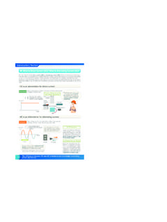
5 (a) Ionic clouds of positive and negative currents. The positiveclouds are normally atoms that lost one or more electrons; the negative clouds are normallyfree electrons. (b) The flow of electrons inside a conductor material, for example, in space or within gases. As it will be shown in later chapters, both typesof electrical conduction are found in turbogenerators. See Figure ELECTRICAL MECHANICAL EQUIVALENCET here is an interesting equivalence between the various parameters describ-ing electrical and mechanical forms of energy. People with either electrical ormechanical backgrounds find this equivalence useful to the understanding of thephysical process in either form of energy. Figure describes the various formsof electrical-mechanical ALTERNATED CIRCUITS (AC)As it will be shown later, alternators operate with both alternating (ac) anddirect- current (dc) electric power. The dc can be considered a particular case ofthe general ac, with frequency equal to frequency of an alternated circuit is measured by the number of times thecurrents and/or voltages change direction (polarity) in a unit of time.
6 The Hertz isthe universally accepted unit of frequency, and measures cycles per second. OneALTERNATED CIRCUITS (AC)7 Fig. equals one cycle per second. Alternated currents and voltages encountered inthe world of industrial electric power are for all practical purposes of constantfrequency. This is important becauseperiodicsystems, namely systems that haveconstant frequency, allow the currents and voltages to be represented a rotating vector. The benefit of using phasors in electrical engi-neering analysis is that it greatly simplifies the calculations required to solvecircuit depicts a phasor of magnitudeE, and its corresponding sinusoidaltrace representing the instantaneous value of the quantitye. The magnitudeErepresents the maximum value a sinusoidal voltage is applied to a closed circuit, a current will flow init. After a while the current will have a sinusoidal shape (this is called thesteady-statecurrent component) and the same frequency as the voltage. An interesting8 PRINCIPLES OF OPERATION OF SYNCHRONOUS MACHINESV oltage (e) E (phasor) Fig.
7 PhasorE, that can represent the voltage impressed on a circuit. The phasoris made of a vector with magnitude proportional to the magnitude ofE, rotating at aconstant rotational speed . The convention is that phasors rotate counterclockwise. Thevertical projection of the phasor results in a sinusoidal representing the instantaneousvoltageeexisting at any time. In the graph, = t, wheretis the time elapsed fromits zero in periodic circuits is that the resulting angle between the appliedvoltage and the current depends on certain characteristics of the circuit. Thesecharacteristics can be classified as beingresistive, capacitive, andinductive. Theangle between the voltage and the current in the circuit is called thepower cosine of the same angle is called thepower factorof the circuit, or for short,the :As it will be shown latter, in synchronous machines the termpower angleis used to identify a different concept. To avoid confusion, in this book the anglebetween the current and the voltage in the circuit will therefore be identified bythe power factor.
8 In the case of a circuit having only resistances, the voltages and currents arein phase, meaning the angle between them equals zero. Figure shows thevarious parameters encountered in a resistive circuit. It is important to note thatresistances have the property of generating heat when a current flows throughthem. The heat generated equals the square of the current times the value of theresistance. When the current is measured in amperes and the resistance in ohms,the resulting power dissipated as heat is given in watts. In electrical machines thisheat represents a loss of energy. It will be shown later that one of the fundamentalrequirements in designing an electric machine is the efficient removal of theseresistive losses, with the purpose of limiting the undesirable temperature rise ofthe internal components of the resistive circuits the instantaneous power delivered by the source to the loadequals the product of the instantaneous values of the voltage and the the same sinusoidal voltage is applied across the terminals of a circuitwith capacitive or inductive characteristics, the steady-state current will exhibitan angular (or time) displacement vis-`a-vis the driving voltage.
9 The magnitudeALTERNATED CIRCUITS (AC)9 Fig. circuits (resistive). Schematic representation of a sinusoidal voltageof magnitudeEapplied on a circuit with a resistive loadR. The schematics shows theresultant currentiin phase with the voltagev. It also shows the phasor representation ofthe voltage and the angle (or power factor) depends on how capacitive or inductive the loadis. In a purely capacitive circuit, the current will lead the voltage by 90 , whilein a purely inductive one, the current will lag the voltage by 90 (see Fig. ).A circuit that has capacitive or inductive characteristics is referred to as beingareactivecircuit. In such a circuit, the following parameters are defined:S: Theapparent power S=E I, given in units ofvolt-amperesor : Theactive power P=E I cos , where is the power angleof the given in units of : Thereactive power Q=E I sin , given in units ofvolt-amperes-reactiveor active powerPof a circuit indicates a real energy flow. This is power thatmay be dissipated on a resistance as heat, or may be transformed into mechanicalenergy, as it will be shown later.
10 However, the use of the word power in thename ofSandQhas been an unfortunate choice that has resulted in confounding10 PRINCIPLES OF OPERATION OF SYNCHRONOUS MACHINESFig. circuits (resistive Inductive Capacitive). Here the sinusoidal volt-ageEis applied to a circuit comprised of resistive, capacitive, and inductive resulting angle between the current and the voltage depends on the value of theresistance, capacitance, and inductance of the individuals without an electrical engineering background for many fact is thatapparent powerandreactive powerdoes not represent any mea-sure of real energy. They do represent the reactive characteristic of a given loador circuit, and the resulting angle (power factor) between the current and angle between voltage and current significantly affects the OPERATION of anelectric machine, as it will be discussed the time being let us define another element of ac circuit analysis: thepower triangle. From the relationships shown above amongS, P, Q, E, I, and , it can be readily shown thatS, P, andQform a triangle.