Transcription of High Voltage Direct Current Tansmission r
1 1 Answers for Voltage Direct Current Transmission Proven Technology for Power Exchange2 3 ContentsChapter Theme Page1 Why high Voltage Direct Current ?42 Main Types of HVDC Schemes63 Converter Theory84 Principle Arrangement of an HVDC Transmission ComponentsThyristor ValvesConverter TransformerSmoothing ReactorHarmonic FiltersAC Harmonic FilterDC Harmonic FilterActive Harmonic FilterSurge ArresterDC Transmission CircuitDC Transmission LineDC CableHigh Speed DC SwitchesEarth ElectrodeControl & Protection141518212223252628313133343638 6 System Studies, Digital Models, Design Specifications457 Project Management46 Why high Voltage Direct Current ?
2 1 from the HighVoltage Direct Current (HVDC) HistoryThe transmission and distribution ofelectrical energy started with directcurrent. In 1882, a 50-km-long 2-kV DCtransmission line was built betweenMiesbach and Munich in that time, conversion betweenreasonable consumer voltages andhigher DC transmission voltages couldonly be realized by means of rotatingDC an AC system, Voltage conversion issimple. An AC transformer allows highpower levels and high insulation levelswithin one unit, and has low losses. It isa relatively simple device, which requireslittle maintenance. Further, a three-phasesynchronous generator is superior to aDC generator in every respect.
3 For thesereasons, AC technology was introducedat a very early stage in the developmentof electrical power systems. It was soonaccepted as the only feasible technologyfor generation, transmission and distri-bution of electrical , high - Voltage AC transmissionlinks have disadvantages, which maycompel a change to DC technology: Inductive and capacitive elements ofoverhead lines and cables put limits to the transmission capacity and the transmission distance of AC trans-mission links. This limitation is of particular signi-ficance for cables. Depending on therequired transmission capacity, the system frequency and the loss eva-luation, the achievable transmission distance for an AC cable will be in therange of 40 to 100 km.
4 It will mainly be limited by the charging Current . Direct connection between two AC systems with different frequencies isnot possible. Direct connection between two AC systems with the same frequency ora new connection within a meshed grid may be impossible because of system instability, too high short-circuitlevels or undesirable power flow were therefore engaged overgenerations in the development of atechnology for DC transmissions as asupplement to the AC Current SourcedConvertersThe invention of mercury arc rectifiers inthe nineteen-thirties made the design ofline-commutated Current sourcedconverters 1941, the first contract for a commer-cial HVDC system was signed inGermany.
5 60 MW were to be suppliedto the city of Berlin via an undergroundcable of 115 km length. The systemwith 200 kV and 150 A was ready forenergizing in 1945. It was never putinto then, several large HVDC systemshave been realized with mercury replacement of mercury arc valvesby thyristor valves was the next majordevelopment. The first thyristor valveswere put into operation in the outdoor valves for Cahora Bassawere designed with oil-immersedthyristors with parallel/series connectionof thyristors and an electromagnetic development went via air-insulated air-cooled valves to the air-insulated water-cooled design, which isstill state of the art in HVDC valve development of thyristors with highercurrent and Voltage ratings has eliminatedthe need for parallel connection andreduced the number of series-connectedthyristors per valve.
6 The development oflight-triggered thyristors has furtherreduced the overall number ofcomponents and thus contributed toincreased in almost every other areaof HVDC have been constantly addingto the reliability of this technology witheconomic benefits for users throughoutthe Voltage SourcedConvertersVoltage sourced converters requiresemiconductor devices with turn-offcapability. The development of InsulatedGate Bipolar Transistors (IGBT) with highvoltage ratings have accelerated thedevelopment of Voltage sourcedconverters for HVDC applications in thelower power main characteristics of the voltagesourced converters are a compact design,four-quadrant operation capability andhigh is offering Voltage sourcedconverters for HVDC applications withratings up to 250 MW under the tradename HVDC plus Power Link paper focuses upon HVDC trans-mission systems with high ratings.
7 Line-commutated Current = high Voltage Direct currentDC= Direct currentAC= alternating currentIGBT = insulated gate bipolar transistor4 Merits of HVDCThe advantages of a DC link over an AClink are: A DC link allows power transmissionbetween AC networks with differentfrequencies or networks, which can not be synchronized, for other reasons. Inductive and capacitive parameters do not limit the transmission capacityor the maximum length of a DC overhead line or cable. The conductorcross section is fully utilized becausethere is no skin a long cable connection, beyond40 km, HVDC will in most cases offerthe only technical solution because ofthe high charging Current of an AC is of particular interest for trans-mission across open sea or into largecities where a DC cable may provide theonly possible solution.
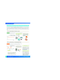
8 A digital control system provides accurate and fast control of the activepower flow. Fast modulation of DC transmission power can be used to damp power oscillations in an AC grid and thus improve the system stability. ConsiderationsFor a given transmission task, feasibilitystudies are carried out before the finaldecision on implementation of an HVACor HVDC system can be taken. Fig. 1-1shows a typical cost comparison curvebetween AC and DC transmissionconsidering: AC vs. DC station terminal costs AC vs. DC line costs AC vs. DC capitalised value of lossesThe DC curve is not as steep as the ACcurve because of considerably lower linecosts per kilometre.
9 For long AC linesthe cost of intermediate reactive powercompensation has to be taken break-even distance is in the rangeof 500 to 800 km depending on a numberof other factors, like country-specific costelements, interest rates for projectfinancing, loss evaluation, cost of rightof way IssuesAn HVDC transmission system is basi-cally environment-friendly becauseimproved energy transmission possi-bilities contribute to a more efficientutilization of existing power land coverage and the associatedright-of-way cost for an HVDC overheadtransmission line is not as high as thatof an AC line. This reduces the visualimpact and saves land compensation fornew projects.
10 It is also possible to in-crease the power transmission capacityfor existing rights of way. A comparisonbetween a DC and an AC overhead lineis shown in Fig. are, however, some environmentalissues which must be considered for theconverter stations. The most importantones are: Audible noise Visual impact Electromagnetic compatibility Use of ground or sea return pathin monopolar operationIn general, it can be said that an HVDC system is highly compatible with anyenvironment and can be integrated intoit without the need to compromise onany environmentally important issues 1-2: Typical transmission line structuresfor approx.