Transcription of Third Function Valve Kit - Land Pride
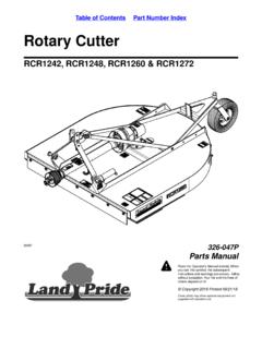
1 1 Figure 1 Notes1. This manual is written with the assumption that the tractor is not supplied with rear remotes or This Valve kit is designed to operate hydraulic For further assistance write to: land Pride Service Box 5060 Salina, Ks. 67402-5060E-mail address: InstructionsInitial Preparations1. Park tractor on a flat surface, place gear shift lever in park, turn off engine, and remove ignition AssemblyRefer to Figure 1 & Figure 2:1. Remove hardware A used to mount the tractor s loader control Valve assembly B .2. Bolt land Pride s Third Function Valve assembly in place by positioning mount bracket (#2) under the tractor s loader control Valve assembly B .3. Reinstall hardware A removed in step 1 to secure land Pride s Third Function Valve as color photos, visit look for " Third Function valves .
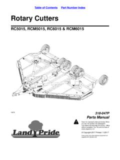
2 "4. Route hydraulic hoses (#12 & #13) under the tractor s platform and back towards the rear of the 2 Connect hydraulic Hoses to Power Beyond Ports1. Locate and remove hydraulic hose that connects power beyond port of tractor s loader Valve assembly to outlet block under the tractor to Figure 2:2. Connect hydraulic hose (#13) from P port of Third Function Valve (#10) to fitting in outlet block where hydraulic hose was removed in step (#1)3. Connect hydraulic hose (#12) from T port of Third Function Valve (#10) to the fitting in the power beyond port of loader Valve where hydraulic hose was removed in step #1 Secure hoses (#12 & #13) to tractor as needed with cable ties (#3).5. Check tractor hydraulic fluid level. If low, add recommended hydraulic fluid.
3 Refer to your tractor Operator's Manual for recommended hydraulic fluid and procedure for checking hydraulic fluid to positive (+) post on the tractor batteryRight-Hand SideLeft-Hand SideT- Po r tP-PortIMPORTANT: land Pride recommends that your dealer connects hydraulic hoses (#12 & #13) to your tractor s power beyond ports. Improper hook-up could cause damage to your tractor or L2501, L3301 & L3901 Kubota Tractors with LA525 LoaderFor L3200 & L3800 Kubota Tractors with LA524 LoaderFor L4600 Kubota Tractor with LA764 LoaderFor L4701 Kubota Tractor with LA765 Loader 380-153M Copyright 2016 Printed5/3/19 Third Function Valve Kit #380-152A Installation Instructions2 Third Function Valve Kit #380-152A Installation Instructions 380-153M 5/3/19 Assembly Instructions Figure 3 Control Lever AssemblyRefer to Figure 3 & Figure 4:1.
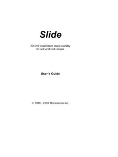
4 Remove existing knob (not shown) from end of control lever C .2. Install new joystick (#14) over end of control lever C with push buttons facing operator as Tighten set screws (#4) against control lever C . Tighten jam nuts (#5) to secure set screws (#4).Refer to Figure 4 Connections A : Connect one black wire in harness (#15) to one black wire in harness (#10) and the other black wire in harness (#15) to one white wire in harness (#10). Connection B : Connect the two red wires from the joystick (#14) to one end of wire (#8) with fuse holder (#16), and connect opposite end of wire (#8) to the positive (+) post on the tractor to Figure 3:6. Secure wiring with cable ties (#3) as Beam Mount For L2501, L3301, L3901, L3200, & L3800 TractorsRefer to Figure 4 & Figure 5:1.
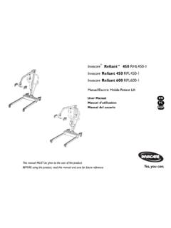
5 Orient bulk head mount (#1) as shown and attach it to right-hand side of loader crossbeam D with u-bolt (#7) and hex whiz nuts (#6). Tighten hex whiz nuts to the proper Beam Mount For L4600, L4701 TractorsRefer to Figure 4 & Figure 6:1. Remove existing top and top rear hardware (#18 & #19) from the right-hand side of loader cross tube E .2. Orient as shown and attach bulk head mount (#17) to right-hand side of loader cross tube E with new x 35 bolt (#19) and new x 20 bolt (#18), lock washers (#20) and flat washer (#21). Tighten bolts (#18 & #19) to the proper Buttons 15414C35 Figure 4 Figure 5 Figure 637118 Attach to positive (+) post on the tractor batteryRight-Hand SideLeft-Hand SideT- Po r tP-Port371201967D37245199172021212018E35 /3/19 Third Function Valve Kit #380-152A Installation Instructions 380-153M Assembly Instructions Figure 7 Hose Routing Along Loader ArmRefer to Figures 4, 5, & 6 on page 2 & Figure 7:1.
6 Route hydraulic hoses (#9) along loader arm and through loader loop bracket F to Third Function Valve assembly (#10).2. Connect hoses to quick couplers (#11) on A & B ports of Valve block (#10).3. Secure hydraulic hoses (#9) as needed with cable ties (#3).371219 FCorporate Office: Box 5060 Salina, Kansas 67402-5060