Transcription of THREE-BEAD-BALUN REFLECTION BRIDGE 250 KHz …
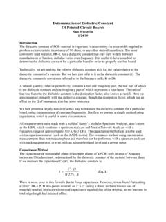
1 THREE-BEAD-BALUN REFLECTION BRIDGE250 KHz to GHzSam paper presents a REFLECTION BRIDGE useful from 250 KHz to the neighborhood of GHz. This BRIDGE may be used in conjunction with a vector network analyzer (VNA), in which case the use of OSL calibration makes its performance about as good as one could want. It may also be used without calibration as a free-standing BRIDGE , as discussed schematic of the BRIDGE is shown in the Appendix. It consists of three parts. The first part is an input attenuator, resistive BRIDGE , and Mini-Circuits TC1-1-13 balun , all on a single PCB. The second part is a homemade balun made with RG-178 coax and three small ferrite beads . This balun is supported by a brass strip, which connects the first and second PCBs.
2 The third part, contained on a second PCB, is an output attenuator and output connector. Because of the homemade balun , I refer to this as the THREE-BEAD-BALUN BRIDGE . The finished BRIDGE is shown in Figure 1 Assembled THREE-BEAD-BALUN BridgeThe ferrite beads are wound in fiberglass tape to keep the coaxloops from shifting over 2 shows a wound ferrite bead before 2-Ferrite bead with three turns of RG-178(Passing once through the center counts as one turn)Theory of OperationThis BRIDGE is a standard resistive BRIDGE , using two ohm resistors (close enough to 50 ohms for present purposes) as the upper legs of two voltage dividers, and using the device under test (DUT) as one lower leg, and an external 50 ohm load as the other lower leg.
3 (The external load is used to preserve symmetry, which is useful at higher frequencies. Below a few hundred MHz, an on-board ohm resistor can be used.) The REFLECTION from the DUT is equal to the difference between the voltage on the DUT and on the 50-ohm reference. That difference is extracted by means of two successive baluns that function as common mode chokes to pass only the differential trick to obtaining decent performance is to have an effective balun . The TC1-1-13 balun by itself can only obtain directivity on the order of 20 db (more on directivity below), and also has weak performance below 5 MHz. Therefore, a second balun is used to further choke the common mode use the BRIDGE as a free-standing device to measure return loss, an input signal is connected to the input and the output is connected to a spectrum analyzer.
4 An open standard is connected to the DUT port, and the output level is recorded. A short standard is then connected to the DUT port, and the output level recorded. The average of the open and short output levels becomes the reference level for that frequency. Various DUTs can then be attached to the DUT port, and the output level recorded. The difference between the DUT output and the reference level (obtained from averaging the open and short), expressed as a positive number in db, is the return loss of the DUT. That return loss measures the REFLECTION received from the DUT relative to the signal sent to the DUT. For example, if the average of the open and short is -12 dbm, and the output with the DUT attached is -30 dbm, then the measured return loss is 30-12=18 dbm.
5 (Error will be discussed later.)The BRIDGE may be used with a vector network analyzer, in which case the use of Open-Short-Load (OSL) calibration will greatly improve accuracy. In addition, the VNA will be able to measure the phase of the REFLECTION , which enables it to determine S-Parameters. PerformanceThe quality of a REFLECTION BRIDGE is measured primarily by its directivity. Directivity is the amount of indicated return loss with a 50-ohm load. There should be no REFLECTION in that situation, so the return loss should be infinite. For use with a VNA directivities of 20 db or better are acceptable, and anything over 30 is nearly perfect. For free-standing use without calibration, a directivity of 30 db will allow measurement of actual return losses up to 30 db, with some uncertainty (more on that later).
6 Another measure of quality is the difference between the open and short output levels. Ideally, the magnitude of the REFLECTION with an open and shorted DUT should be equal. A discrepancy between them may indicate that the DUT port does not present a good 50-ohm impedance to the DUT. When directivity is good and the open and short are close to one another, the DUT port impedance is likely very close to 50 3 shows the measured directivity and open/short for the THREE-BEAD-BALUN BRIDGE . Note that while we subtract the short output from the open output to determine open/short, we are subtracting db levels so the resulting difference actually represents the ratio of the open and short outputs. Hence the label open/short.
7 Open/short magnitudes can be as high as db without presenting a serious 3 Directivity and open/shortFigure 3 shows that the directivity is good from 250 KHz to somewhere near GHz, and is excellent from 1 MHz to 1 GHz. The open/short value exceeds db at only two small peaks for frequencies below DUT port should ideally present a 50-ohm impedance to the DUT. If any part of the REFLECTION reaching the DUT port is itself reflected back to the DUT, the measurement of the REFLECTION will be inaccurate. When the BRIDGE is used with a VNA, calibration will correct for this error, unless it becomes unreasonably large. For free-standing use of the BRIDGE , DUT port return losses of 30 db or better are acceptable.
8 The open/short value can be used as a guide to whether return loss is getting out of hand, but the correlation is not perfect. Figure 4 shows the measured return loss of the THREE-BEAD-BALUN BRIDGE , using a technique described later. This technique does not pin down the exact return loss, but does indicate the worst that the return loss can be. In the case of Figure 4, the technique could only be used up to 300 MHz:Figure 4 Return Loss of DUT Port to 300 MHzFigure 4 shows that the return loss is extremely good from 250 KHz to 300 MHz. Given the open/short and directivity values, I would expect this good return loss to continue beyond 1 GHz, possibly dipping below 30 db briefly around 450 Return Loss ManuallyA REFLECTION BRIDGE can be used to measure return loss manually, as described above under Operation.
9 The question arises as to how accurate such measurements are, given the lack of OSL calibration, which a VNA would perform. First, consider how much accuracy is needed. Return loss indicates the amount of power reflected by the DUT. Generally, if the DUT has return loss of 30 db or better (higher), it is reflecting so little power that it does not really matter exactly how little it is. Or in terms of impedance, return loss of 30 db or better means the impedance of the DUT is close enough to 50 ohms that it can be considered to be 50 ohms. For example, resistances between 47 and 53 ohms have return losses of 30 db or the other hand, if a DUT reflects half or more of the power reaching it, we may just consider it to be unacceptable, without having to know exactly how much it reflects.
10 A DUT with a return loss of 3 db or worse (lower) reflects at least half the power reaching if we know the return loss is higher than 30 db or lower than 3 db, that may be all we need to know. And even for values in the 3-30 db range, errors of several db may not be one situation where precision might be useful is to determine the exact impedance of the DUT, for example in order to devise an impedance matching network to adjust it to 50 ohms. However, because return loss is a scalar value, we cannot determine the exact impedance even if we knew the exact return loss. Phase information would be required. Our manual use of the BRIDGE provides only scalar information, and is effectively a scalar network analyzer , as opposed to the fancier vector network analyzers , which provide phase information.