Transcription of Three -Phase PFC Rectifier with Phase - Modular Y ...
1 Three - Phase PFC Rectifier with Phase - Modular Y- Rectifier for LED Lamp Narin Watanakul* Thammasat University of Thailand, Faculty of Engineering, Department of Electrical and Computer Engineering, Rangsit Campus, Klong Luang, Pathumthani, Thailand Abstract The paper was to study ac/dc Three Phase PFC Rectifier for LED lamp. The performance normally of the Rectifier having is current low quality and low power factor and high total harmonics distortion current. Therefore, the objectives in this a paper going to improving power factor and reduce harmonics current. In this paper to propose power factor correction (PFC) with Phase - Modular Y- Rectifier , boost type converter circuit using by one cycle control (OCC). For high performance method and tested of the result for realize that can solve power factor and reduce harmonic current.
2 The research papers, conclusions for study and evaluate the circuit can be operation and suitable for use with LED 50 W (LED lamp). The data collected by MATLAB Simulation are used in comparison with the experimental tester of results. Keyword- LED Lamp, Phase - Modular Y- Rectifier , Harmonics reduction, Power factor correction, Switch-mode rectifiers (SMRs), Improved power quality converters (IPQCs). I. INTRODUCTION In 1990's ultra-bright LEDs using Aluminium Indium Gallium Phosphide (AlInGaP) to produce orange-red, orange, and yellow and presently green light has become available. The first significant blue LEDs also appeared at the start of the 1990's, once again using Silicon Carbide - a throwback to the earliest semiconductor light sources, although like their yellow Russian ancestors the light output was very dim by today's standards.
3 Ultra bright blue Gallium Nitride (GaN) LEDs arrived in the mid-1990s, with Indium Gallium Nitride (InGaN) LEDs producing high-intensity blue and green shortly thereafter ( [1]-[3]). In Fig 1, shows the current range of LED, which can take many forms and depending on the manufacturer. The package tube LED (LED package) Surface Mouth Type rated 50 watt, 30 volt level rang and the current rating of the LED about of current use 20-50 mA , 50-150mA and current 150mA-1000mA. Example, the current range of LED on type of production. In a theoretical case where output current can be estimated as clean DC current. The diode bridge connects the capacitor to the AC source when the voltage is near the peak, resulting in an abridged sinusoidal shaped current wave with current only flowing for about 1 to 2ms every half cycle.
4 To deal with this type of nonlinear load the term apparent power factor evolved. The inclusion of the word apparent implies a nonlinear load and hence a non-sinusoidal current. the harmonic current frequencies of a single Phase and Three Phase Rectifier are n times the fundamental frequency (50 or 60 Hz). The current wave shape is not a pure sinusoid. Harmonic currents and voltages are created by non-linear loads connected on the power distribution system. Harmonic distortion is a form of pollution in the electric plant that can cause problems if the sum of the harmonic currents increases above certain limits. The input current is now in Phase with input voltage and the converter looks like a resistor from the AC power line. For example, the Apparent Power Factor must be > for loads >50% of full load rating.
5 This is usually expressed as limits for odd harmonics ( 1st, 3rd, 5th, 7th, etc.). This approach does not need any qualifying minimum percentage load and is more relevant to the electric utility as their main interest is to ensure that a particular installation can safely supply any current a load may demand. Regulatory specifications, such as EN61000-3-2/EN61000-4-7 utilize this method. As was shown in Fig. 2 and , Depicts the effects of this circuit with the same power being delivered to a power factor corrected supply for a non-PFC unit. Narin Watanakul / International Journal of Engineering and Technology (IJET)ISSN : 0975-4024 Vol 7 No 5 Oct-Nov 20151788 This paper to propose Y- Rectifier in a Three Phase star connection technique based power LED driver topology.
6 The Three Phase balance Phase current AC/DC Rectifier with the control can make it the input line current of power converter with the unity power factor, and the current waveform distortion results increase of the lower harmonics distortion. II. POWER FACTOR AND THD Conventionally, ac dc converters, which are also called rectifiers, are developed using diodes and thyristors to provide controlled and uncontrolled dc power with unidirectional and bidirectional power flow. They have the demerits of poor power quality in terms of injected current harmonics, caused voltage distortion and poor power factor at input ac mains and slow varying rippled dc output at load end, low efficiency and large size of ac and dc filters. (a) (b) (c) Fig.
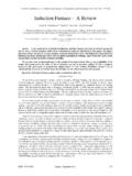
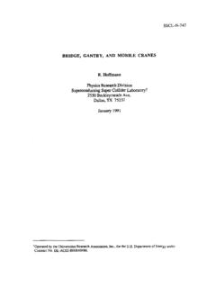
7 2, Depicts the effects of current quality this circuit with the single Phase rectifies ( 4 - pulses ) being delivered to a power factor corrected supply for a non-PFC unit. (a) (b) (c) Fig. 3, Depicts the effects of current quality this circuit with the Three Phase rectifies (6 - pulses) being delivered to a power factor corrected supply for a non-PFC unit. In Fig 2(c), shows the harmonic content of the current waveform is percentage of total harmonic distortion (%THDi) approximately 84%. The capacitor (Cd) will only charge when Vs(V) is greater than its stored voltage ,meaning that a non-PFC circuit will only charge (Cd) a small percentage of overall cycle time. After 90 degrees ( (b)),the half cycle from the bridge drops below the capacitor voltage (Cd),which back biases the bride, inhibiting current flow into the capacitor (via Vs).
8 In Fig 3(c), shows the harmonic content of the current waveform is percentage of total harmonic distortion (%THDi) approximately 109%. The Power Quality (PQ) in electrical systems is regulated by IEC and EN standards, used as reference by the utilities ( [4]-[6]). Therefore, a good understanding of the LEDs harmonic production characteristics becomes necessary. Many studies about the PQ issues related to the lighting devices have been addressed to analyze these problems as in [7]. The new breed of rectifiers has been developed using new solid state self-commutating devices such as gate turn-off thyristors (GTO), MOSFETs, insulated gate bipolar transistor (IGBTs),etc., even some of which have either not been thought or not possible to be developed earlier using diodes and thyristors.
9 Such pieces of equipment are generally known as converter, but specifically named as switch-mode rectifiers (SMRs), power-factor correctors (PFCs), PWM rectifiers converter, multilevel rectifiers, etc. (a) (b) Narin Watanakul / International Journal of Engineering and Technology (IJET)ISSN : 0975-4024 Vol 7 No 5 Oct-Nov 20151789 VI=Total Apparent Power (c) (d) Fig. 4, Example, Harmonics with significant any amplitude in the AC side voltage waveform (a) shows input current and fundamental of current (n =1), (b) and (c) shows detail harmonic current waveform n = 1,3,5,7,11 and (d) show phases of diagram power harmonic. A power quality analysis has been performed to compare the different luminaries behavior.
10 The absorbed apparent power is decomposed in four different parts, as described as in [7] with regards to the single -Phase case (shows in and ). The RMS values of voltage and current are decomposed, respectively, where subscript 1 refer to the fundamental harmonic as: 11()cossinDCnnnnVt Van tbn t ===++ (1) 11()cossinDCnnnnItIa nt b nt ===++ (2) ()1/ Vn=++++ (3) ()1/ I I I In=++++ (4) The dimensionless index of the total harmonic distortion (THD) present and it is defined, The total harmonic distortion of a signal is for current and voltage respectively, as in [7]: ()1/ VnTHDV+++= (5) ()1/ InTHDI+++= (6) The apparent power is decomposed into fundamental apparent power(S1),current distortion power (DI),voltage distortion power (DV), and harmonic apparent power (SH) as in [7].