Transcription of Three-View, Plan View and Elevation View Drawings
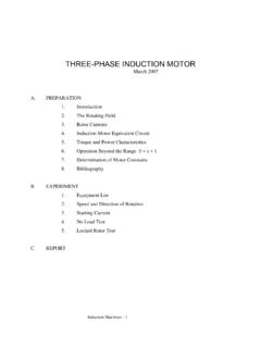
1 chapter Three-View, Plan View and Elevation View Drawings Technical Drawings are the language engineers and architects use to communicate their ideas and designs to journeymen. It is a language based on lines and s:m- bols that have specific meanings. Journeymen must possess the sldll to interpret these symbols and lies, so that they may install and maintain piping systems. This chapter discusses the use of three-view draw- ings, section Drawings , and schematic Drawings , and introduces some special-purpose Drawings , such as ex- ploded Drawings and wiring diagrams. The photograph in Fig. 2-1 clearly depicts the over-all appearance of a concrete block. A three-view drawing will most clearly show the appearance as well as the exact size and other details of construction of an object.
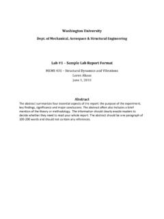
2 The three-view drawing of the concrete block shown in Fig. 2-2 is a drawing with the Top View posi- tioned directly above the Front View and the Right- Side or Left-Side View positioned directly to the right or left of the Front View. The Front View of the concrete block in Fig. 2-2 Top View Front View Right-Side View Also, the Right-Side View in Fig. 2-2 does not repre- sent what is usually considered the "Right-Side" of the concrete block. The key to understanding the relationship of the views in a three-view drawing is the Front View. The Front View locates the object directly in front of the viewer. See Fig. 23. '3 does not show what is normally considered the Front View. : -1 The Front V~ew in a 3 View drawing does not neces- sarily show the -front" of an object How, then, is the Right-Side to the Front View?
3 View related Fig. 2-6 is a three-view drawing of a concrete block.. With the Front View directly in front of the viewer, the Right-Side View is what the viewer would see if he or she were to walk to their right until the right side of the object was directly in front of them. See Fig. 24. - Top View Front View Riqht-Side View 1 11 1 Front View B R~ght-Slde V~ew How would the Top View be related to the Front View? The TOP View in Fig. 2-5 shows the object as the On squared block Paper, sketch the viewer would see it when they stand at the Front View, as concrefe block in three views as shown in shown in Fig. 24, and look directly down on the object. fig. 2-6. use a straight edge and a medium-weight pencil. Note the equal TOP View spacing at "A" and "6." Save these sketches for future reference.
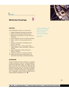
4 The drauing in Fig. 2-6 does not give a complete un- derstanding of the object. Only the visible details in each view are shown. In a three-view drawing, solid limes are used to rep- resent the details of an object which can be seen in each view. Broken lines are used to illustrate the openings which are "hidden" in the Front and Right-Side Views. See Fig. 2-7. rnnrr-vrrw, 1-LAN VlLW AND Elevation VIEW Drawings 3 TOP View The Front View, Top View, and the Right- ; Side View in Fig. 2-7 must be compared to get a true picture of the "hidden" , details. I TOP View r Front View Right Side View Using the Top View shown in Fig. 2-8 as the Right-Side View, make a second sketch and compare it with Fig. 2-9. The three-view Drawings which have been discussed are generally accepted as standard in the United States and TOP View On squared block paper, make a three- view drawing of the concrete block with the Front View being what is normally Front Right Side considered as the front of the block.
5 View View Compare your drawing with the one shown in Fig. 2-8. Canada, but other views may be shown which would better illustrate the object. See Fig. 2- 10. Top View I Front View Right Side View Finished Wall Line The water closet shown in Fig. 2-11 is taken from an actual rough-in book. The Front View of the drawing in Fig. 2-11 shows the left side of the fixture. In Fig. 2-11, the left side of the fixture was chosen as the Front View because the left side of the fixture con- tains the ballcock and the rough-in could best be shown by this view. The Top View- of the fixture in Fig. 2-11 was omitted because the Front View, Right-Side View, and related notes provide sufficient information to rough-in this particular type water closet. Technical Drawings don't always show three views or all of the hidden lines and the exact outside shape of an object.
6 If space is at a premium, the draftsman may use symbols to represent objects such as valves or pipe fit- tings. Y8'' Supply to Floor When Specified NOTE: This Water Closet is Designed to Rough-in at a Min. Dimension of 12" From Finished Wall to Q of Outlet Fig. 2-12-A, B and C are Drawings of a 90" elbow shown in three views. An example of a 90" elbow is shown in Fig. 2-12-6 and C using symbols. Q Top View @ Top View Front Right Sid- Front Right Side View View View View A Q Top View Front Right Side View Mew C In the process of making a drawing of a complicated piping system, the use of symbols similar to the types shown in Fig. 2-13 obviously saves time and space. You must know what these symbols stand for if you are to understand what the draftsman is trying to convey in a drawing.
7 Tee Looking Away From Viewer 1 Check Valve r 1 Reducer or Increaser PD Tee Looking Toward Viewer On squared block paper, sketch a three- view drawing, using fitting symbols, to illustrate the piping arrangement shown in Fig. 2- 15. Each symbol in Fig. 2-13 is both correctly identified Compare your sketch with the one shown in Fig. I and pictured by a double line drawing in Fig. 2-14. 2-16. 17 Note: The "Fitting Face Marks" are omitted in Fig. 2-16. 0 Fitting Face Marks should only be used on a sketch or drawing when they are needed for clarification. Figs. 2-17, 2-18 and 2-19 are the front, right side, and top views of a pneumatic water booster system. Fig. 2- 20 is the same system drawn in an isometric view with the use of fitting symbols. Symbols are used in Fig. 2-20 which represent the pumps, valves and fittings.
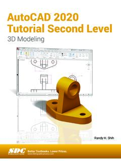
8 From observation it be- comes obvious that the use of symbols require far less effort than drawing each item in the three views of the pneumatic water booster system shown in Figs. 2-17,2- 18 and 2-19. THREE-VIEW, PLAN VIEW AND Elevation VIEW Drawings THREE-VIEW, PLAN VIEW AND Elevation VIEW Drawings The type of Drawings most commonly used on job sites are plan and Elevation views. Usually the plan and one Elevation view are used to fully describe an object, however in some instances more than one Elevation view is needed. Explain. The plan view is the view as seen from above the ob- ject, looldng down on it or the top view. The Elevation view is the view from one side of the object. Fig. 2-21 is an example of this type of drawing, showing the plan view, four Elevation views and the bottom view.
9 Each one of these views shows two of the principle dimensions and can show only two. The front view or front Elevation shows the width and height of the front of the object. The top view or plan view shows the width and length of the top. The right side view or right Elevation shows the length and height of the right side. The left view or left Elevation shows the length and height of the left side. The rear view or rear Elevation shows the width and height of the rear side. The bottom view is not a plan view, but rather it is a view from beneath the object looking up. This view shows the length and width of the underside of the ob- ject. This view is not often used in pipe Drawings , but is sometimes used to show the bottom side of such things as vessels, turbines, etc. You must remember that this view is from the bottom looking up.
10 The plan view is often used to show the floor plan of a building or equipment room. Usually the plan view shows the building with the roof removed and the ob- server is looking down at the floor or floor plan. Fig. 2-21 shows the correct method for arranging these six views. When sketching pipe, how should these rules be observed? 1. The top view or plan view should be placed di- rectly above the front view. 2. The bottom view should be drawn directly below the front view. 3. The right view should be drawn directly to the right of the front view. 4. The left view should be drawn directly to the left of the front view. 5. The rear view should be drawn to the left of the left view or if necessary to the right of the right view. While some views can be omitted: no view should be drawn in any other position.