Transcription of TIMBER FRAMING - National Park Service
1 TIMBER FRAMINGJOURNAL OF THE TIMBER FRAMERS GUILDN umber 71, March 2004 Historic Queenpost TrussesTIMBER FRAMINGJOURNAL OF THE TIMBER FRAMERS GUILDNUMBER 71 MARCH 2004 CONTENTSQ&A: A BRACING EXCHANGE2C. Bremer, R. Christian, C. Hoppe, G. Mullen, J. Miller, B. Popenoe, B. WormingtonTIMBER FRAMING FOR BEGINNERS 4 VIII. WHENROOFSCOLLIDE2 Will BeemerHISTORIC AMERICAN ROOF TRUSSES12II. QUEENPOSTTRUSSESJan LewandoskiHISTORIC QUEENPOST TRUSS ANALYSIS21Ed LevinFRAMING THE MONTEBELLO PAVILION23 Oliver Amandi, Markus BrunnTIMBER FRAMING , Journal of theTimber Framers Guild, reports on thework of the Guild and its members,and appears quarterly, in March, June,September and December. The journalis written by its readers and pays forinteresting articles by experienced andnovice writers 2004 TIMBER Framers Guild, PO Box 60, Becket, MA Correspondence PO Box 275, Newbury, VT 05051802-866-5684 RowerContributing EditorsGuild Affairs Will Beemer, Joel McCartyHistoryJack A.
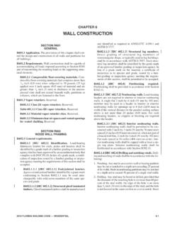
2 Sobon TIMBER Frame DesignEd LevinPublished Quarterly. Subscription $25 annuallyor by membership in the TIMBER Framers 1061-9860 On the cover, views of the queenpost truss FRAMING in the atticof the Congregational Church, Peacham, Vermont, 1806. Majormembers are of high-quality spruce and pine; the smaller braces,remarkably profuse, are of mixed hardwoods. Floor is camberedlengthwise as well as transversely to produce a shallow dome inthe ceiling below. White spots are frost. Photos by Ken Rower. TIMBER FRAMING 71 MARCH 2004 Clark Bremer, Minneapolis. Many of the plans in TIMBER framingbooks show both braces in the plane of the bent on almost everyinterior post of a bent section. But the same is not true of bracesperpendicular to the bent. They always seem to be there in exteri-or walls, but on the interior posts they are often omitted. Is therea reason for this? Let s say I m planning a small house with fourbents, each with three posts.
3 That s 12 posts, where only two ofthem are interior. All of the possible knee braces are in place,except for the ones on these two interior posts. On these two inte-rior posts, there are eight possible knee braces. I d like to omit twoof them, one on each post, perpendicular to the bent plane. Doesthat seem reasonable? Rudy R. Christian, Burbank, Ohio. It s worth noting that bracesare usually placed in pairs. The purpose of bracing is to withstandintermittent transverse loading. The stress of raising is one exam-ple. Wind and snow are others. Wind loads are hard to predict,both in strength and direction. By placing braces in opposed pairs,one works to resist the wind from one direction while the otherrests. When the wind switches direction, the opposite occurs. Inmany early barns, braces were not pegged, which indicates theearly framer s understanding of the work a brace does: resisting aforce in compression.
4 Moving a brace to keep it paired is the bestsolution. If you have to remove one, it s likely you should removeits mate also. Having an engineer look at the drawings is, of course,the most dependable solution. Chris Hoppe, Athens, Knee braces are not often found per-pendicular to the bent at the center post because FRAMING is basedlargely on tradition and the old hay barns did not have a timberrunning perpendicular to the bent at the top of the center post.(The center post usually terminated at the bottom of the tie beam.)A second reason is that in new frames the joists often run perpen-dicular to the bents and, to avoid conflicting joints, it s best toavoid having a joist arrive at the same location as the center there may be no member to brace to, whereas at the eaves thereis usually a heavy plate available. An engineer can help make aninformed decision on the number and location of braces required.
5 Grigg Mullen, Lexington, Va. One of the main purposes of thebraces is to resist racking of the frame because of wind loads. Loadsapplied parallel to the bents strike a much larger exterior surfacearea (usually including the roof ) than loads perpendicular to thebents, where there s only the end wall to catch wind, and the bracesin several bents to resist that load. The braces are generally not asheavily loaded in this direction, and it s possible that one set can beomitted without compromising the stability of the Miller, Floyd, Va. It s worth noting in any discussion of knee braces that the tensioncreated in the joint braced is usually the limiting factor in theireffectiveness. It s often the case that more braces do not make abuilding stronger. Any structure begins failing at its weakest s where attention should be & AA Bracing ExchangeTIMBER FRAMING 71 MARCH 2004 Bart Popenoe, Hood River, Oregon.
6 For purposes of resolving thestatic forces acting in a TIMBER frame through its braces, an engi-neer tells me that I should treat a brace as if it were a post, anddivide the supported beam above into two separate beams: onebeam between the post and brace, and another between the braceand the next post. But if this were true, braces would almost alwaysbe carrying huge loads and would have to be some of the largesttimbers in a TIMBER frame. Inspection tells me this is not the the other hand, the authors of a book on TIMBER engineering Ijust read consider braces strictly as members for resisting lateralloads wind, seismic, etc. When they calculate for beam size, jointshear and the like, they size the beams as if the braces weren t eventhere. They conclude that considering the braces for weight-bear-ing is dubious, since beam shrinkage likely increases the distancesthat braces need to span and braces stay the same length.
7 Thismakes much more sense to me, although I think that the truth liessomewhere between both methods. Rudy R. Christian. My understanding of the correct use of bracesis that that they serve in pairs (in general). The loading conditionthat requires bracing, wind for example, will likely work frommore than one direction. The effect is that braces in pairs actuallyfunction as one brace. When a lateral load is applied to the system,one half of the brace pair goes into compression while the othergoeson vacation. When this condition occurs, the brace indeed canassume a tremendous load, but in true compression, allowing asmall-section member to do a great deal of work. The TIMBER thataccepts the load from the brace, however, normally ends up deal-ing with bending and shear forces. For this reason I have beentaught to think of braces more as pry bars than posts. My experience with barn frames has shown that braces doindeed resist static loading as well as dynamic.
8 Braced purlins are agood example. The braces are typically opposed at the purlin posts,which allows them to work directly against one another (no bend-ing), and the brace legs are appropriately increased in length withthe span of the purlin. Of course, this pairing doesn t work at thegable load study, I do consider it practical to reduce thespan of a member by one brace leg if the member is braced at bothends. If it s only braced on one end, as in your example, the spancannot be reduced. Conversely, if the brace is pegged, you maywant to increase the loading factors for the beam since, from timeto time, the brace may end up in tension. Bart m engineering the joinery for a TIMBER -framedgarage-loft design , 24x28, with a principal rafter-common purlin12/12 roof and kingpost truss bents with a 24-in. kneewall. I vebeen using the Guild s Joinery & design Workbookas well as othertexts to educate myself.
9 Everything was going great until I startedtrying to resolve the forces being carried by the knee braces. Specifically, my design uses a strut between the principal rafterand tie beam to reduce the roof load at the end posts. This strut,in worst case scenario on the center bent, transfers 8721 lbs. of roofload to the 8x10 tie beam at 40 in. from its end and offset 8 the knee brace below. I have been told that the entire 8721lbs. should be transferred directly to the brace, which sounds to melike it may cause some problems with bending stresses on the post,as well as requiring one honkin big brace. I ve seen this strut solu-tion used on many larger frames without abnormally large braces,so I think that this approach must be in Wormington, Great Barrington, Mass. Don t worry. I thinkthe problem of how much vertical load the brace carries is more afunction of the tightness of the joinery than of the actual geome-try.
10 If the brace is a little undersized, it will carry nothing untilthere is enough bending in the cross beam to load it and then startto share the load with the end support (vice versa for an oversizedbrace). Wood is very strong in compression parallel to the grain(from the NDS[ National design Specification] tables, the value is1500-2000 psi for most species). If you assume 1500 psi, you donly need sq. in. of cross-section to support your entire 3x5 brace would have almost three times this of the load sharing effect, I think even an undersized bracewould never fail. Bart Popenoe. Hmmm .. My NDStables show design values forcompression parallel to the grain generally in the 350-900 psirange. For my species, Ponderosa pine, the allowable compressionparallel to the grain is 700 psi for #1 posts, and 325 psi for #2 posts,which will place me closer to allowable limits if I use a 4x6 brace(8721 24 sq.)