Transcription of Time Delay Relay Function Guide
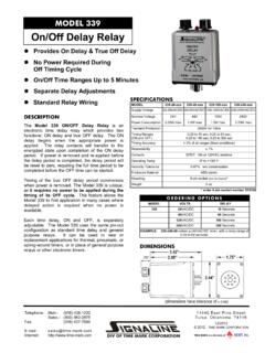
1 Please contact us at or 855-289-9676 Product Compliance and Suitability. THE PRODUCT STATEMENTS CONTAINED IN THIS EZTIP ARE INTENDED FOR GENERAL INFORMATIONAL PURPOSES ONLY. SUCH PRODUCT STATEMENTS DO NOT CONSTITUTE A PRODUCT RECOMMENDATION OR REPRESENTATION AS TO THE APPROPRIATENESS, ACCURACY, COMPLETENESS, CORRECTNESS OR CURRENTNESS OF THE INFORMATION PROVIDED. INFORMATION PROVIDED IN THIS EZ TIP DOES NOT REPLACE THE USE BY YOU OF ANY MANUFACTURER INSTRUCTIONS, TECHNICAL PRODUCT MANUAL OR OTHER PROFESSIONAL RESOURCE OR ADVISER AVAILABLE TO YOU. ALWAYS READ, UNDERSTAND, AND FOLLOW ALL MANUFACTURER INSTRUCTIONS. If you are still having difficulty choosing a time Delay Relay , Document Create Date: 1 March 2015 Zoro time Delay Relay eZtip Last Review: 23 March 2015 2011 - 2015 Zoro Tools, Inc. All rights reserved. Information sources include Grainger, Square D, and Dayton time Delay Relay Function Guide Function Code Description of time Delay Operation 1 ON Delay : When power is APPLIED to the coil, the ON Delay timing period begins.
2 The contacts do not transfer at this time . At the end of the ON Delay time period the contacts transfer, either connecting (normally open contacts) or disconnecting (normally closed contacts) the load. The contacts stay in the transferred state until power is REMOVED from the coil. They then return to their original state and the unit is ready for a new cycle. 2 OFF Delay I: Power is applied to the coil at all times. Upon CLOSURE of the start switch (a "dry" external contact), the contacts transfer, either connecting (normally open contacts) or disconnecting (normally closed contacts) the load. When the start switch is OPENED, the OFF Delay timing period begins. The contacts stay in the transferred position until the OFF Delay timing period ends. They then return to their original position and the unit is ready for a new cycle. 3 OFF Delay II: Power is applied to the coil at all times. Upon the MAKE and RELEASE of the start switch (a "dry" external contact), the OFF Delay timing period begins and the contacts transfer, either connecting (normally open contacts) or disconnecting (normally closed contacts) the load.
3 When the timing period ends, the contacts return to their original position and the unit is ready for a new cycle. 4 INTERVAL Delay : When power is APPLIED to the coil (the start switch must be jumped in multifunction timers), the INTERVAL timing period begins and the contacts transfer, either connecting (normally open contacts) or disconnecting (normally closed contacts) the load. When the INTERVAL timing period ends, the contacts return to their original position. The unit resets when power is removed from the coil, making the unit ready for a new cycle. 5 CYCLE 1 SHOT (EQUAL time OFF/ON): Upon application of power to the timer, timing starts. The output Relay is OFF for the set time and then ON for the set time for 1 cycle only. The timer is reset when power is removed or a reset input is applied. 6 REPEAT CYCLE (EQUAL ON AND OFF Delay time PERIODS): When power is APPLIED to the coil, the OFF time period is initiated; the contacts do not transfer.
4 At the end of the OFF time period, the ON time period begins. The contacts transfer, either connecting (normally open contacts) or disconnecting (normally closed contacts) the load. At the end of the ON period, the contacts transfer and the cycle continues until power is removed from the coil. 7 REPEAT CYCLE (INDEPENDENT ON AND OFF Delay time PERIODS): When power is APPLIED to the coil, the ON period is initiated by contact transfer (normally open contacts close, normally closed contacts open). At the end of the OFF period, contacts release and the ON period begins. The cycle continues until power is removed from the coil. 8 SIGNAL INTERVAL/OFF Delay : Power is applied to the coil at all times. Upon CLOSURE of the start switch (a "dry" external contact), the INTERVAL cycle begins; the contacts transfer, either connecting (normally open contacts) or disconnecting (normally closed contacts) the load. At the end of the INTERVAL cycle, the OFF Delay cycle begins and the contacts stay transferred until the OFF Delay cycle ends.
5 The contacts then return to their original positions and the unit is ready for a new cycle. 9 SIGNAL ON Delay /OFF Delay : Power is applied to the coil at all times. Upon CLOSURE of the start switch (a "dry" external contact), the ON Delay cycle begins; the contacts do not transfer. At the end of the ON Delay cycle the contacts transfer, either connecting (normally open contacts) or disconnecting (normally closed contacts) the load. Upon RELEASE of the start switch, the OFF Delay cycle begins; the contacts remain transferred. At the end of the OFF Delay cycle, the contacts return to their original positions and the unit is ready for a new cycle. 10 POWER OFF Delay : When power is APPLIED to the coil, the contacts transfer, either connecting (normally open contacts) or disconnecting (normally closed contacts) the load. When power is removed from the coil, the OFF Delay timing period begins; contacts remain transferred. At the end of the OFF Delay cycle, the contacts return to their original positions and the unit is ready for a new cycle.
6 11 WATCHDOG (RETRIGGERABLE SINGLE SHOT): Upon application of input voltage, the time Delay Relay is ready to accept trigger signals. Upon application of the trigger signal, the Relay is energized and the preset time begins. At the end of the preset time , the Relay is de-energized unless the trigger signal is closed and opened prior to time out (before preset time elapses). Continuous cycling of the trigger signal at a rate faster than the preset time will cause the Relay to remain energized. time Delay Relays are used to control the flow of electrical power. A time Delay Relay is a combination of an electromechanical output Relay and a control circuit. These relays are pre-engineered to perform up to 11 time Delay functions . The list below contains the Function code and description of each of the time Delay Relay functions . On the manufacture s specification sheet for the time Delay Relay , one of the specifications will be named Function Codes and will be followed by numbers 1 through 11.
7 This will designate each Function that particular Relay can perform. Many of the relays have a knob to control the adjustable time Delay Function . A control signal is fed into to the Relay and starts the Relay Function . The electrical power at the input of the Relay is then allowed to switch the output of the Relay at the appropriate times. time Delay relays can be used to control power to many different types of electrical loads.