Transcription of Time Temperature Transformation (TTT) Diagrams
1 Time Temperature Transformation (TTT) DiagramsR. MannaAssistant ProfessorCentre of Advanced StudyDepartment of Metallurgical EngineeringInstitute of Technology, Banaras Hindu UniversityVaranasi-221 005, Steel-TRAERF Faculty Fellowship Visiting ScholarDepartment of Materials Science and MetallurgyUniversity of Cambridge, Pembroke Street, Cambridge, CB2 diagramsTTT diagram stands for time- Temperature - Transformation diagram. It is also called isothermal Transformation diagramDefinition: TTT Diagrams give the kinetics of isothermal of TTT diagram for eutectoid ( )techniquescombinedwithmetallographyandh ardnessmeasurement,dilatometry( ),electricalresistivitymethod,magneticpe rmeability,insitudiffractiontechniques(X -ray,neutron),acousticemission,thermalme asurementtechniques, 2 : Bath II low- Temperature salt-bath for isothermal 1 : Salt bath I -austenitisation heat.
2 3(a): Sample and fixtures for dilatometric measurements Fig. 3(b) : Dilatometer ( )ismaintainedataustenetisingtemperature( 780 Cforeutectoidsteel).SaltbathII( )ismaintainedatspecifiedtemperatureatwhi chtransformationistobedetermined(belowAe 1),typically700-250 +20-40 Cforeutectoidandhypereutectoidsteel,AC3+ ,t2,t3,t4, , ,aswellasquantityofphases, ,saypearliteorbainiteisconsideredastrans formationstarttimeandfor99% , (whiteappearanceinopticalmicroscope). (white). (230 Cforplaincarboneutectoidsteel)isconsider edasthemartensitestarttemperature(design atedMS).ThetemperatureofbathIIatwhich99% martensiteisformediscalledmartensitefini shtemperature(MF).
3 : Time Temperature Transformation (schematic) diagram for plain carbon eutectoid steelt1t3t2t4t5MF, Martensite finish temperatureM50,50% MartensiteMS,Martensite start temperatureMetastable austenite +martensiteMartensite% of Phase0100 TemperatureLog timeHardnessAe1T2T150%T2T1 PearliteFine pearliteUpper bainiteLower bainite50% very fine pearlite + 50% upper bainiteAt T1, incubation period for pearlite=t2,Pearlite finish time =t4 Minimum incubation period t0at the nose of the TTT diagram, t0MS=Martensite start temperatureM50= Temperature for 50% martensite formationMF= martensite finish temperature9At close to Ae1temperature, coarse pearlite forms at close to Ae1temperature due to low driving force or nucleation rate.
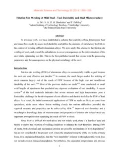
4 At higher under coolings or lower Temperature finer pearlite the nose of TTT diagram very fine pearlite formsClosetotheeutectoidtemperature, ,astheundercoolingincreasestransformatio nacceleratesuntilthemaximumrateisobtaine datthe nose C (sayT1)thetransformationstartsafteraninc ubationperiod(t2,atT1). (t3atT1)fordifferenttemperaturesiscalled 50% (t4atT1)iscalledtransformationfinish, ,50%and99% ( ). 5(a) : The appearance of a (coarse) pearlitic microstructure under optical (b):Acabbagefilledwithwateranalogyofthet hree-dimensionalstructureofasinglecolony ofpearlite, 5(c): Optical micrograph showing colonies of pearlite.
5 Courtesy of S. S. 5(d): Transmission electron micrograph of extremely fine 5(e): Optical micrograph of extremely fine pearlite from the same sample as used to create Fig. 5(d). The individual lamellae cannot now be 6: Time Temperature Transformation (schematic) diagram for plain carbon eutectoid steelMFM50 MSMetastable + MMTemperatureLog timeHardnessAe1 PFPUBLB50% very FP + 50% UBMetastable =austenite =ferriteCP=coarse pearliteP=pearliteFP=fine pearliteUB=upper bainiteLB=lower bainiteM=martensiteMS=Martensite start temperatureM50= Temperature for 50% martensite formationMF= martensite finish temperature17 Oncoolingofmetastableaustenite1%martensi teformsatabout230 (characteristicamountoftransformationcom pletesinaveryshorttime)
6 Diagram givesNature of Transformation -isothermal or athermal (time independent) or mixedType of Transformation -reconstructive, or displaciveRate of transformationStability of phases under isothermal Transformation conditionsTemperature or time required to start or finish Transformation Qualitative information about size scale of product Hardness of transformed products19 Factors affecting TTT diagramComposition of steel-(a) carbon wt%, (b) alloying element wt%Grain size of austeniteHeterogeneity of austeniteCarbon wt%-AsthecarbonpercentageincreasesA3decr eases,similaristhecaseforAr3, ,Acmlinegoesup, , , (a)-(b) 7(a) :Schematic TTT diagram for plain carbon hypoeutectoid steelMFM50 MSMetastable + MMTemperatureLog timeHardnessAe1 +CP +PFPUBLBFP + UB =austenite =ferriteCP=coarse pearliteP=pearliteFP=fine pearliteUB=upper BainiteLB=lower BainiteM=martensiteMS=Martensite start temperatureM50= Temperature for 50% martensite formationMF= martensite finish temperatureAe3t0 Metastable 22 Fig.
7 7(b): Schematic TTT diagram for plain carbon hypereutectoid steelM50 MSMetastable Metastable + MTemperatureLog timeHardnessAe1Fe3C+CPFe3C+PFe3C+FPUBLB very FP +UBAecmt0 =austeniteCP=coarse pearliteP=pearliteFP=fine pearliteUB=upper BainiteLB=lower BainiteM=martensiteMS=Martensite start temperatureM50= Temperature for 50% martensite formation23 Fig. 8: Schematic Fe-Fe3C metastable equilibrium diagram and TTT Diagrams for plain carbon hypoeutectoid, eutectoid and hypereutectoid steelsMS(a) Fe-Fe3C metastable phase diagram(b) TTT diagram for hypoeutectoid steel(c ) TTT diagram for eutectoid steel(d)
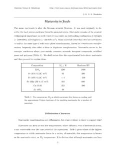
8 TTT diagram for hypereutectoid steel =austenite =ferriteCP=coarse pearliteM=martensiteMS=Martensite start temperatureM50= Temperature for 50% martensite formationMF= martensite finish temperatureP=pearliteFP=fine pearliteUB=upper bainiteLB=lower bainite24 Underisothermalconditionsforvariouscompo sitionsproeutectoidtranformationhasbeens ummarisedbelow( ).Inhypoeutectoidsteeltheobservableferri temorphologiesaregrainboundaryallotriomo rph( )( (a)-(d)),Widmanst ttenplate( W)( ),andmassive( M)ferrite( (f)). % martensiteMix martensiteLath martensiteMSMFV olume % of retained austenite at room temperatureVolume % of retained austeniteFig 9: Temperature versus composition in which various morphologies are dominant at late reaction time under isothermal condition WCmW MUpper bainiteLower bainiteW=Widmanst tten plate M=massiveP=pearlite ub=upper bainite lb =lower bainite26 Thereareoverlappingregionswherebothequia xedferriteandWidmanst 10: The reconstructive and displacive mechanisms.
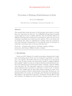
9 28 Fig. 11(a): schematic diagram of grain boundary allotriomoph ferrite, and intragranular idiomorph (b): An allotriomorph of ferrite in a sample which is partially transformed into and then quenched so that the remaining undergoes martensitic Transformation . The allotriomorph grows rapidly along the austenite grain boundary (which is an easy diffusion path) but thickens more (c) ; -particlesmightbeidentifiedasidiomorphs, (d) (e):Anidiomorphofferriteinasamplewhichis partiallytransformedinto andthenquenchedsothattheremaining 11(f ): Massive ferrite ( m) in wt%C alloy quenched into ice brine from 1000 C.
10 Courtesy of T. B. Massalski34 Fig. 12(a): Schematic illustration of primary Widmanst ttenferrite which originates directly from the austenite grain surfaces, and secondary wwhich grows from (b):Opticalmicrographsshowingwhite-etchi ng(nital)wedge-shapedWidmanst (noticethescale) 13: The simultaneous growth of two self-accommodating plates and the consequential tent-like surface : Transmission electron micrograph of what optically appears to be single plate, but is in fact two mutually accommodating plates with a low-angle grain boundary separating them. alloy, austenitisedat 1200C for 6 hrs, isothermally transformed at 700C for 2 min and water 15: Mixture of allotriomorphic ferrite, Widmanst tten ferrite and pearlite.