Transcription of TLK 48 MICROPROCESSOR-BASED DIGITAL …
1 1 TLK 48 MICROPROCESSOR-BASED DIGITAL electronic REGULATOR TECHNICAL DATA CARATTERISTICHE MECCANICHE Housing Self-extinguishing plastic, UL 94 V0 Dimensions 48x48 mm DIN depth 98 mm Weight 225 g approx. Connections 2x1 mm2 screw terminal block Mounting Flush in panel in 45,5x45,5 mm hole Front panel protection IP 54 mounted in panel with gasket ELECTRICAL DATA Power supply 24, 115, 230 VAC +/-10% AC Frequency 50 / 60 Hz Power consumption 5 VA approx. INPUT DATA Thermocouple J, K, S According to IEC 584-2 accuracy class 1 or 2 Thermoresistance Pt 100 According to IEC 751 accuracy class A or B Infrared sensors TECNOLOGIC IRS J and K Thermistor PTC KTY 81-121 (990 at 25 C) ; NTC 103AT-2 (10 k at 25 C) Current input 0 mA Voltage input mV, mV, mV, 0 V, 0 V Normalized signals input impedance 0 mA: 51 mV and V: 1 M OUTPUT DATA Relay outputs Up to 2 outputs SPST-NO (8 A-AC1, 3 A-AC3 / 250 VAC) Voltage output for SSR driving Up to 2 outputs : 8 mA at 8 VDC with protection against short circuits Auxiliary power supply output 10 VDC / 20 mA max FUNCTIONAL DATA Control ON/OFF, Neutral Zone, PID single and double action programmable Overall accuracy + fs Display resolution According to the used probe 1/0,1/0,01/0,001 Measurement range According to the used probe and to the measurement unit Unit of measurement C - F, programmable Max.
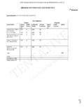
2 Cold junction compensation drift C/ C with operating temperature C after warm-up of 20 min. Measure sampling time 130 ms Display 4 digit red h=12 mm Parameters access Protected by password Operating temperature C Operating humidity RH% without condensation 2 MEASUREMENT RANGE PROBE RANGE 4 DIGIT RANGE 4 DIGIT with PROBE RANGE 4 DIGIT RANGE 4 DIGIT with tc J SEnS = J -160 .. 1000 C -256 .. 1832 F --- mA SEnS = -1999 .. 9999 .. tc K SEnS = CrAl -270 .. 1370 C -454 .. 2498 F --- mV SEnS = -1999 .. 9999 .. tc S SEnS = S -50 .. 1760 C -58 .. 3200 F --- mV SEnS = -1999 .. 9999 .. Pt 100 SEnS = Pt1 -200 .. 850 C -328 .. 1562 F .. C .. F SEnS = -1999 .. 9999 .. PTC SEnS = Ptc -55 .. 150 C -67 .. 302 F .. C .. F V SEnS = -1999 .. 9999 .. NTC SEnS = ntc -50 .. 110 C -58 .. 230 F .. C .. F V SEnS = -1999 .. 9999 .. mV SEnS = -1999 .. 9999 .. V SEnS = -1999 .. 9999 .. mA SEnS = -1999.
3 9999 .. V SEnS = -1999 .. 9999 .. ALARM OUTPUTS The alarm functioning is depending on the Process Value and it s programmable through a 4 figures code; depending on the value of the suitable parameters, it s possible to have 6 different types of alarms : Alarm type Alarm output 1 Absolute Low alarm: it s activated when the Process Value is lower than the alarm threshold 2 Absolute High alarm: it s activated when the Process Value is higher than the alarm threshold 3 Absolute Low band alarm: it s activated when the Process Value is lower than the low alarm threshold or higher than the high threshold alarm 4 Low Deviation alarm: it s activated when the Process Value is lower than (SetP+ low threshold) 5 High Deviation alarm: it s activated when the Process Value is higher than (SetP+ high threshold) 36 Deviation band alarm: it s activated when the Process Value is lower than (SetP+low threshold) and higher than (SetP+ high threshold) Alarms hysteresis The alarms functioning is influenced by the hysteresis phenomenon which works asymmetrically.
4 In case of low alarm, the alarm is activated when the Process Value goes under the threshold alarm and it s deactivated when the Process Value goes upper than the alarm threshold; in case of high alarm, it s viceversa. LOOP BREAK alarm function The LB alarm is needed to segnalise the interruption of the control loop, because of a thermocouple shortcircuit or inversion or interruption of the load. RAMP FUNCTION The function of ramp and fall it s needed to reach the Set Point value within a predefined time, which has to be programmed in advance and has to be necessarily longer than the one of the process controlled. The meaning of this function is not to place under thermical stress the treated materials. Once the instrument has reached the first Set Point (SP1) it s possible to have the automatic commutation on the second Set Point (SP2) after a programmed time, with a simple automatic cycle. That function is available for all the programmable control types.
5 CONTROL MODE FEATURES ON / OFF CONTROL This control works on output 1rEG, depending on the Set Point, on the functioning mode and on the hysteresis programmed. The control is symmetrical or asymmetrical. Symmetrical means that the output is ON untill when the Process Value has reached (SP+hysteresis) or when has reached (SP-hysteresis).Asymmetrical means that the output is ON up to the reaching of the Set Point, to become again ON when it has reached (SP-hysteresis). NEUTRAL ZONE CONTROL This type of control concerns both outputs and it is used to control a plant which is equipped with a heating and a refrigerant element. This control works on the outputs depending on the measure, on the Set Point and on the hysteresis programmed. 4 PID CONTROL The PID control works with a particular algorithm with two degrees of freedom that optimises, in independent way, the features of the instrument, in case of process noises and Set Point variations.
6 PID CONTROL Single action PID CONTROL Double action The single action PID control works on the output 1rEG depending on the active Set Point, on the functioning mode and on the instrument s PID algorithm with two degress of freedom. The double action PID is obtainable when 2 outputs are programmed respectively 1rEG and 2rEG and is used to control plants where there is an element which causes a positive increment (ex. Heating) and an element which causes a negative increment (ex. Cooling). This type of control works on the outputs 1rEG and 2rEG depending on the active Set Point and on the instrument s PID algorithm with two degrees of freedom. PARAMETERS PROGRAMMING PARAMETERS PROGRAMMING Proportional band 0 .. 9999 Proportional band 0 .. 9999 Manual reset .. Manual reset .. Output 1rEG cycle time .. s Output 1rEG cycle time .. s Integral action time OFF .. 9999 s Output 2rEG cycle time.
7 S Derivative action time OFF .. 9999 s Integral action time OFF .. 9999 s Fuzzy Overshoot Control .. Derivative action time OFF .. 9999 s Fuzzy Overshoot Control .. Prat: Ratio between cooling power and heating power The parameter Fuzzy Overshoot Control permits to avoid the variable overshoots at the start up of the process or at the changing of the Set Point. AUTOTUNING FUNCTION This function permits to automatically tune the PID parameters, after the Set Point programming. The calculated values are automatically stored, at the end of the Autotuning cycle, into the PID parameters. That function permits the PID parameters calculation through a tuning cycle FS type and, at the end of this operation, the parameters are stored into the instrument s memory and remain constants during the control. The Autotuning cycle duration has been limited at 12 hours maximum. SELFTUNING FUNCTION It s an algorithm that permits to calculate the PID parameters during the control.
8 It has the meaning to correct the control errors caused by the process variations. It s type rule based TUNE-IN and automatically recognises the type of noise and works in order to optimise the control, reducing as much as possible the oscillations. SOFT-START FUNCTION That function is only workling with PID control and allows the limiting of the control power when the instrument is switched on, for a programmable time. This is useful when the actuator, driver by instrument, could be damaged by power too high supplied when the application is not yet in the normal rating. When the Soft-Start is active, it s not possibile to execute the Autotuning, because it may gives an excessive power. 5 MECHANICAL DIMENSIONS (mm) FRONT PANEL DESCRIPTION 1 - Key P It s used to get into the parameters programming and to confirm the programmed parameter. 7 Led SET Lighted, it signalises the input in programmation mode. 2 - Key DOWN In the programming phase, it decreases of one unit the figure on which it s located the slider.
9 In the normal functioning, it visualises the current measured by input TA HB. 8 - Led AT/ST If it s flashing, the instrument is executing the AUTO-TUNING. If it s permanently lighted the instrument is executing the SELF-TUNING. 3 Key UP In the programming phase, it increases of one unit the figure on which it s located the slider. In the normal functioning, it visualises the output control power. 9 - Led (-) Shift index It indicates that the process value is lower than as programmed Set. 4 Key U Key with function programmable as: Activate Autotuning and Selftuning funcions, swap the instrument into manual control, aknowledge the alarm, change the active Set Point, deactivate the control. 10 Led (=) Shift index It indicates that the process value is within the programmed range. 65 Led OUT1 Lighted, it signalises that output OUT1 is active. 11 Led (+) Shift index It indicates that the process value is higher than as programmed Set. 6 Led OUT2 Lighted, it signalises that output OUT2 is active.
10 CONNECTIONS DIAGRAM CERTIFICATIONS AND CONFORMITY CE Conformity: CEE EMC 89/36 (EN 61326) CEE LT 73/23 and 93/68 (EN 61010-1) UL CONFORMITY: File n. E 206847 TECNOLOGIC Indipendenza,56 27029 Vigevano ITALY TEL. +39 038169871 FAX +39 0381698730 e-mail.