Transcription of TLSZ Guardmaster Guard Locking Switch User Manual
1 User ManualOriginal InstructionsTLSZ Guardmaster Guard Locking SwitchCatalog Numbers 440G-TZS21 UPRH, 440G-TZS21 UPLH, 440G-TZS21 UTRH, 440G-TZS21 UTLH2 rockwell automation Publication 440G-UM002B-EN-P - December 2021 TLSZ Guardmaster Guard Locking Switch User ManualImportant User InformationRead this document and the documents listed in the additional resources section about installation, configuration, and operation of this equipment before you install, configure, operate, or maintain this product. Users are required to familiarize themselves with installation and wiring instructions in addition to requirements of all applicable codes, laws, and including installation, adjustments, putting into service, use, assembly, disassembly, and maintenance are required to be carried out by suitably trained personnel in accordance with applicable code of this equipment is used in a manner not specified by the manufacturer, the protection provided by the equipment may be no event will rockwell automation , Inc.
2 Be responsible or liable for indirect or consequential damages resulting from the use or application of this examples and diagrams in this Manual are included solely for illustrative purposes. Because of the many variables and requirements associated with any particular installation, rockwell automation , Inc. cannot assume responsibility or liability for actual use based on the examples and patent liability is assumed by rockwell automation , Inc. with respect to use of information, circuits, equipment, or software described in this of the contents of this Manual , in whole or in part, without written permission of rockwell automation , Inc., is this Manual , when necessary, we use notes to make you aware of safety labels may also be on or inside the equipment to provide specific following icon may appear in the text of this : Identifies information about practices or circumstances that can cause an explosion in a hazardous environment, which may lead to personal injury or death, property damage, or economic : Identifies information about practices or circumstances that can lead to personal injury or death, property damage, or economic loss.
3 Attentions help you identify a hazard, avoid a hazard, and recognize the information that is critical for successful application and understanding of the HAZARD: Labels may be on or inside the equipment, for example, a drive or motor, to alert people that dangerous voltage may be HAZARD: Labels may be on or inside the equipment, for example, a drive or motor, to alert people that surfaces may reach dangerous FLASH HAZARD: Labels may be on or inside the equipment, for example, a motor control center, to alert people to potential Arc Flash. Arc Flash will cause severe injury or death. Wear proper Personal Protective Equipment (PPE). Follow ALL Regulatory requirements for safe work practices and for Personal Protective Equipment (PPE).Identifies information that is useful and can help to make a process easier to do or easier to automation Publication 440G-UM002B-EN-P - December 20213 Table of ContentsAbout This Publication .. 5 Who Should Use This Manual .
4 5 Summary of Changes.. 5 Additional Resources .. 5 Terminology .. 6 Chapter 1 General DescriptionGuardmaster TLSZ Guard Locking Switch Overview.. 7 Catalog Numbers .. 7 Packaging Contents .. 8 Chapter 2 InstallationGeneral Considerations.. 9 Actuator/Target Mounting .. 9 Allowable Approach Directions .. 9 Minimum Operating Radius .. 10 Manual Release .. 10 Manual Override Cover .. 11 Pair Proximity .. 11 Guide Repositioning .. 11 Steel Locking Bolts .. 12 Actuator Clearance .. 12 Dimensions .. 13 Chapter 3 WiringConnections .. 15 OSSD Inputs .. 15 OSSD Outputs .. 15 Auxiliary Output .. 16 Lock Command .. 16 Chapter 4 CommissioningPreparation .. 17 First Time Power-up .. 18 Learn First Target .. 18 Learning Additional Targets .. 19 Commissioning Errors .. 19 Power-up Self-check.. 20 Chapter 5 Functional TestingTesting Procedure.. 21 Chapter 6 Application and Wiring ExamplesWiring to GLP Relay .. 23 Circuit Status as Shown.
5 244 rockwell automation Publication 440G-UM002B-EN-P - December 2021 Table of ContentsWiring to GLT Relay .. 24 Circuit Status as Shown .. 25 Wiring to DI and EMD Relay .. 26 Circuit Status as Shown .. 27 Wiring to DG Relay .. 27 Wiring to CR30 Relay.. 28 Wiring to 1734 POINT Guard I/O .. 31 Wiring to 1732 ArmorBlock.. 35 Chapter 7 Diagnostics and TroubleshootingTools Needed .. 39 Required Tools .. 39 Optional Tools.. 39 Flowchart .. 40 Step 1 Status Indicator Off .. 40 Step 2 Status Indicator Flashing Red at 4 Hz .. 41 Wrong Target .. 41 Missing Target .. 41 Target Not Mounted Correctly .. 42 Pair Proximity.. 42 Mechanical Pressure on Safety Gate .. 42 Long Wiring .. 43 Voltage Supply Dips .. 44 Rapid Locking .. 44 Step 3 - Status Indicator Flashes Red at 1 Hz .. 45 Capacitive Loading .. 45 Step 4 Status Indicator Flashes Green at 1 Hz.. 45 Corrective Action: .. 46 Step 5 Flashing Red and Green .. 46 Step 6 Indicator Steady Red.
6 46 Step 7 Other Considerations .. 46 Distribution Block .. 46 GSR Relays on Power-up .. 48 Appendix ASpecificationsSafety Ratings .. 49 Operating Characteristics.. 49 Environmental .. 50 General .. 50 Index .. 51 rockwell automation Publication 440G-UM002B-EN-P - December 20215 PrefaceAbout This PublicationThis Manual is a reference guide for the Guardmaster TLSZ Guard Locking Switch . This Manual : Explains how to install and wire your TLSZ Guard Locking Switch . Provides an overview of the Guardmaster TLSZ Guard Locking Should Use This ManualUse this Manual to design, install, program, or troubleshoot systems that use the TLSZ Guardmaster Guard Locking safety are required to have a basic understanding of electrical circuitry and familiarity with safety-related control systems. If you do not, obtain the proper training before using this of ChangesThis publication contains the following new or updated information. This list includes substantive updates only and is not intended to reflect all ResourcesThese documents contain additional information concerning related products from rockwell can view or download publications at p i c P a g eUpdated Table 416 ResourceDescriptionGuardmaster Configurable Safety Relay Wiring Diagrams, publication440C-WD001 Provides example wiring diagrams for the CR30 software configuration safety automation Wiring and Grounding Guidelines, publication general guidelines for installing a rockwell automation industrial Safety Data Sheet, publication SAFETY-SR001 Provides functional safety data and details for rockwell automation automation Glossary, publication of industrial automation terms and abbreviationsProduct Certifications website.
7 Declarations of conformity, certificates, and other certification automation Publication 440G-UM002B-EN-P - December 2021 PrefaceTe r m i n o l o g yThe Industrial automation Glossary contains terms and abbreviations that are used by rockwell automation to describe industrial automation systems. Table 1 lists specific terms and abbreviations that are used in this 1 - TerminologyTermDescriptionNCNo (Normally Closed)An electrical contact whose normal state (for example, no pressure or electrical potential applied) is in the closed (Normally Open)An electrical contact whose normal state (such as no pressure or electrical potential applied) is in the open programmable logic controller or a programmable automation (Power to Lock)Apply 24V to the lock command to lock the Switch . This command applies to the TLSZL Guard Locking Switch . PTL (Power to Release)Apply 24V to the lock command to unlock the Switch . This command applies to the TLSZR Guard Locking TimeDescribes the time between the true state of the input to the on state of the TimeDescribes the time between the trigger of the input to the off state of the output.
8 Throughout this Manual , the safety outputs are described as turning off immediately. (turning off within the response time).RFIDR adio frequency (Output Signal Switching Device)Typically a pair of solid-state signals pulled up to the DC source supply. The signals are tested for short circuits to the DC power supply, short circuits to the DC common, and short circuits between the two codingSame as low coding as defined in EN ISO 14119:2013 TLSZLTLSZ Power to Lock Guard Locking switchTLSZRTLSZ Power to Release Guard Locking switchUnique codingSame as high coding as defined in EN ISO 14119:2013 rockwell automation Publication 440G-UM002B-EN-P - December 20217 Chapter 1 General DescriptionGuardmaster TLSZ Guard Locking Switch OverviewThis Guardmaster TLSZ Guard Locking Switch functions by Locking it actuator, which prohibits the opening of a TLSZ Guard Locking Switch uses radio frequency identification, RFID, coding to detect the appropriate version of the Guardmaster TLSZ Guard Locking Switch features OSSD outputs.
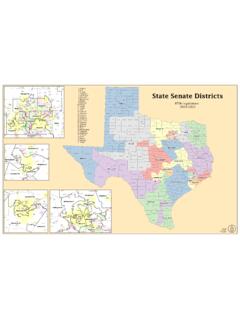
9 These outputs are enabled only when the actuator is locked and the RF target is device is intended to be part of the safety-related control system of a machine. Perform a risk assessment before installation to determine whether the specifications of this device are suitable for all operational and environmental characteristics of the machine. See Specifications on page 49 for certification information and nonremovable screws, bolts, or nuts to mount the Switch and actuators. Do not over torque the mounting Guard Locking switches are classified according to ISO 14119 as Type 4 switching devices. The RFID targets are classified as having a high level of measures to minimize the need to defeat and to manage the use and availability of spare RFID NumbersTable 2 - TLSZ Catalog Number Setup440 GTZS21 UPRH abcdefghiabcCodeDescriptionCodeDescripti onCodeDescription440 Safeguards the productGGuard Locking switchTTitan Locking Switchde fLock TypeConnection TypeSpecial FeaturesCodeDescriptionCodeDescriptionCo deDescriptionZPLe rated, cascadable safety signalsS21 Solid-state outputs, 2 safety (OSSD), 1 auxUUnique coded RFID target8 rockwell automation Publication 440G-UM002B-EN-P - December 2021 Chapter 1 General DescriptionPackaging ContentsFigure 1 shows the contents in the shipping package.
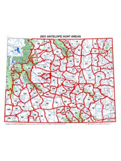
10 The contents include: Switch Actuator RFID target T20 security Torx bit Two steel bolts and nuts Plug Installation instructions (not shown)Figure 1 - Package Contentsde fLock TypeConnection TypeSpecial FeaturesCodeDescriptionCodeDescriptionCo deDescriptionPAux signal shows lock statusRPower to ReleaseH8-pin M12 QD connectorTAux signal shows door statusLPower to LockATTENTION: Guard Locking switches that use the Power to Lock principle can only be used after a risk assessment shows that the Power to Release principle is inappropriate for the application. If a power supply loss occurs with Power to Lock switches, the switches immediately unlock and you can access the automation Publication 440G-UM002B-EN-P - December 20219 Chapter 2 InstallationGeneral ConsiderationsThe TLSZ Guard Locking Switch is designed for use on guards that are engineered to be rigid and without sag. The TLSZ Guard Locking Switch uses radio frequency identification (RFID) coding to detect the appropriate MountingFigure 2 shows the correct and incorrect ways to mount the target with the TLSZ Guard Locking Switch must only be used with the fully flexible actuator.