Transcription of TM 9-4910-679-14&P TECHNICAL MANUAL OPERATOR’S ...
1 TM 9-4910-679-14&PTECHNICAL MANUALOPERATOR S, ORGANIZATIONAL, DIRECT SUPPORTAND GENERAL SUPPORT MAINTENANCEMANUAL INCLUDING REPAIR PARTS LISTFORGRINDING KIT, VALVE SEAT ELECTRICNO. 6335-69(BLACK AND DECKER MFG. CO.)(NSN 4910-00-060-9983)HEADQUARTERS, DEPARTMENT OFTHE ARMYAUGUST 1981TM 9-4910-679-14&PTechnical ManualHEADQUARTERSDEPARTMENT OF THE ARMYNo. 9-4910-679-14&PWashington, DC, 6 August 1981 OPERATOR S, ORGANIZATIONAL, DIRECT SUPPORTAND GENERAL SUPPORT MAINTENANCE MANUALINCLUDING REPAIR PARTS LISTFORGRINDING KIT, VALVE SEAT ELECTRICNO. 6335-69 NSN 4910-00-060-9983 REPORTING ERRORS AND RECOMMENDING IMPROVEMENTSYou can help improve this MANUAL .
2 If you find any mistakes or if you know of a way to improve theprocedures, please let us know. Mail your letter, DA Form 2028 (Recommended Changes to Publicationsand Blank Forms), or DA Form 2028-2, located in the back of this MANUAL direct to: Commander, US ArmyArmament Materiel Readiness Command, ATTN: DRSAR-MAS, Rock Island, IL 61299. A reply will befurnished directly to MANUAL is published for the purpose of identifying an authorized commercial MANUAL for the use of thepersonnel to whom this grinding kit is by: Black and Decker E. Joppa RoadTowson, MD 21204 Procured under Contract No.
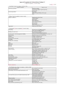
3 DAAA09-77-C-6148 This TECHNICAL MANUAL is an authentication of the manufacturers commercial literatureand does not conform with the format and content specified in AR 310-3, MilitaryPublications. This TECHNICAL MANUAL does, however, contain available information that isessential to the operation and maintenance of the 9-4910-679-14&PINSTRUCTIONS FOR REQUISITIONING PARTSNOT IDENTIFIED BY NSNWhen requisitioning parts not identified by National Stock Number, it is mandatory that the following information befurnished the supply Manufacturer s Federal Supply Code Number 074292 Manufacturer s Part Number exactly as listed Nomenclature exactly as listed herein, including dimensions.
4 If Manufacturer s Model Number 6335-695 Manufacturer s Serial Number (End Item)6 Any other information such as Type, Frame Number, and Electrical Characteristics, if If DD Form 1348 is used, fill in all blocks except 4, 5, 6, and Remarks field in accordance with AR Form as Follows:(a) In blocks 4, 5, 6, list manufacturer s Federal Supply Code Number -07429 followed by a colon andmanufacturer s Part Number for the repair part.(b) Complete Remarks field as follows:Noun: (nomenclature of repair part)For: NSN: 4910-00-060-9983 Manufacturer: Black and Decker E.
5 Joppa RoadTowson, MD 21204 Model: 6335-69 Serial: (of end item)Any other pertinent information such as Frame Number,Type. Dimensions, 9-4910-679-14&PSAFETY RULES FOR POWER WORK AREA CLEAN. Cluttered areas and benches invite DANGEROUS ENVIRONMENT. Don t expose power tools to rain. Don t use power tool in damp or wetlocations. And keep work area well CHILDREN AWAY. All visitors should be kept safe distance from work IDLE TOOLS. When not in use, tools should be stored in dry, high or locked-up place-out of reach T FORCE TOOL It will do the job better and safer at the rate for which it was RIGHT TOOL.
6 Don t force small tool or attachment to do the job of a heavy duty PROPER APPAREL. No loose clothing or jewelry to get caught in moving parts. Rubber gloves andfootwear are recommended when working SAFETY GLASSES with most tools. Also face or dust mask if cutting operation is T ABUSE CORD. Never carry tool by cord or yank it to disconnect from receptacle. Keep cord from heat, oiland sharp WORK. Use clamps or a vise to hold work. It s safer than using your hand and it frees both hands tooperate T OVERREACH. Keep proper footing and balance at all TOOLS WITH CARE.
7 Keep tools sharp at all times, and clean for best and safest instructions for lubricating and changing TOOLS. When not in use, before servicing; when changing accessories such as blades, bits,cutters, ADJUSTING KEYS AND WRENCHES. Form habit of checking to see that keys and adjustingwrenches are removed from tool before turning it ACCIDENTAL STARTING. Don t carry plugged-in tool with finger on switch. Be sure switch is "OFF" whenplugging USE EXTENSION CORDS-When tool is used outdoors, use only extension cords suitable for useoutdoors and so NOT OPERATE portable electric tools in gaseous or explosive atmospheres.
8 Motors in these tools normallyspark, and the sparks might ignite tool is powered by a motor. Be sure your power supply agrees with nameplate marking. VOLTS 50/60 Hz meansAlternating Current (25 to 60 cycles) ONLY. VOLTS DCe60 Hz means it will also operate on Direct Current. Voltagevariation of more than 10% will cause loss of power and over-heating. All tools are factory-tested; if this tool does notoperate, check the power Brushes should be regularly inspected for wear if your tool has exterior Brush Inspection Caps. UNPLUG TOOL first. When the cap is unscrewed, the spring and brush assembly may be withdrawn from the tool.
9 Keep brushes cleanand sliding freely in their guides. Carbon brushes have varying symbols stamped into them, and if the brush is worn downto the line closest to the spring, they must be replaced. New brush assemblies are 9-4910-679-14&PGROUNDINGThis tool should be grounded while in use to protect the operator from electric shock. The tool is equipped with anapproved three-conductor cord and three-prong grounding type plug to fit the proper grounding type receptacle. The green(or green and yellow) conductor in the cord is the grounding wire. Never connect the green (or green and yellow) wire to alive terminal.
10 If your unit is for use on less than 150 volts, it has a plug like that shown in Figure A. If it is for use on 150 to250 volts, it has a plug like that shown in Figure D. An adapter, Figures B and C, is available for connecting Figure A plugsto two-prong receptacles. The green-colored rigid ear, lug, etc, must be connected to a permanent ground such as aproperly grounded outlet box. No adapter is available for a plug as shown in Figure D. Adapter shown in Figures B and Cis not for use in recommend that you NEVER disassemble the tool or try to do any rewiring in the electrical you be determined to make a repair yourself, remember that the green colored wire is the "grounding" wire.