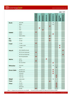
Transcription of TM INCRA IBOX read and follow all of the instructions and ...
1 Manufactured by Taylor Design Group, Inc. Box 810262 Dallas, TX 75381 2022 by Taylor Design Group, Inc. All rights n e r s safety instructions for using the INCRA IBOXSAFETYB efore using the INCRA IBOX, read and follow all of the instructions and safety infor-mation in this owner s delicate 1/8 fingers to bold 3/4 joints to exciting new box joint variations, your New INCRA IBOX is designed to provide the perfect resource for your next joinery task. The dual-pitch lead screw driven positioning engine controls both pin width and spacing with a single adjustment knob while INCRA s GlideLOCK adjustable miter bar provides smooth tracking at either your table saw or router table. Before using your New IBOX, please take the time to read this manual and be sure to watch the included DVD for some exciting new box joint techniques, tips and .. 1 Preliminary Setup.
2 2 Setting up at the Table Saw .. 3 Setting up at the Router Table .. 4 Stock Ledges, Blade Guards & Backing Board .. 5 Operations Cutting a Box Joint .. 7 Tips and Techniques .. 12 Before using the INCR A IBOX, read and follow all instructions and safety information in this manual. When using the INCR A IBOX in conjunction with any other tool, first read and follow all instructions and safety information in that tool s ow ner s ma nu a l. Always turn off the power and make sure that the bit or blade is fully stationary before moving any part of the INCR A IBOX to any new setting. Always use a wooden handscrew clamp to secure your workpiece to the INCR A IBOX before making any cut. Before making a cut, always make sure that the blade guards are in place and that the fasteners that secure the stock ledges and blade guards are securely tightened. Wear safety glasses, hearing protection and follow all normal shop safety practices. When using the INCR A IBOX with other tools, make sure that all safety guards and other safety equipment supplied by the manufac- turer of that tool are securely in place and functional.
3 Never let the INCR A IBOX interfere with another tool s safety equipment. Keep hands safely clear of the bit or blade. DO NOT alter or modify the INCR A IBOX Do not attempt to use the INCR A IBOX with a wobble dado blade. Do not attempt to use the INCR A IBOX with any cutter smaller t h a n 1/8 . If using with a SawStop table saw, put the SawStop in the Bypass Mode before calibrating, adjusting, or checking blade clearances. Return it to normal operation before making a cut. To avoid contacting the metal IBox Fence body with your blade, DO NOT use depth of cut settings greater than 7/8 . INCRA IBOX OWNER S MANUALM anufactured by Taylor Design Group, Inc. Box 810262 Dallas, TX 75381 Page 2 PRELIMINARY SETUPB efore beginning setup at the table saw or router table, make sure that the silver micro-adjust knob is adjusted so that the set screw in the slotted hole on the red knob is aligned approximately centered on the engraved line. This is the home position and while not every setup may require this home position, it is a good place to start when moving the IBOX to a new station.
4 To reset, first loosen the black positioning lock knob located on the top of the IBOX. Hold the red knob in place as you rotate the silver micro-adjust knob until you see the set screw aligned as shown in Detail 1A. While the black positioning lock knob is still loose, rotate the red knob to bring the (2) pin plates together as shown in Detail 1B. You ll see the pin plates located just inside the fence cutout. After adjusting, tighten the black positioning lock knob, Fig. 1. Now let s get set up at your work station. If you are setting up at the table saw, read the Setting up at the Table Saw section that follows. For the router table, jump ahead to Setting up at the Router Table beginning on page 1 Preliminary Setup2) Hold red knoband rotate silver knob to move set screw to home position1) Loosen lock knobDetail 1 ADetail 1 BSet screw at home positionBring pin platestogetherINCRA IBOX OWNER S MANUAL 2022 by Taylor Design Group, Inc. All rights reserved. Page 3 SETTING UP AT THE TABLE SAW1.
5 Install Stack Dado or Box Joint Blade of Choice After completing the preliminary setup described on page 2, unplug your table saw and install your preferred box joint blade. The INCRA IBOX works with standard stack dado sets as well as 2-piece reversible blade box joint sets like those produced by Forrest, Ridge Carbide and Freud. You can cut delicate 1/8 box joints using standard 1/8 kerf table saw blades, but you ll want to choose a blade that features a flat ground raker tooth or a special box joint grind like those from Forrest and Ridge Carbide, Fig 2. If you are setting up one of the reversible blade sets, begin with the widest cut profile for the setup that follows. You can change back to a narrow cut blade configuration later after the setup is complete. If you are setting up with a standard stack dado set, any cut width can be used during Adjust GlideLOCK Miter Bar Assembly Drop the GlideLOCK Miter Bar Assembly into your table saw s miter slot. Use the left-hand slot for left tilting saws or the right-hand slot for right tilting saws.
6 Now adjust the GlideLOCK expansion discs at each end of the bar to adjust the fit for a smooth glide in your table saw s miter slot. Turn the fasteners clockwise to make the glide tighter or counter-clockwise for a looser glide, Fig. 3. The alignment plate is factory squared but can be adjusted as required by loosening the (2) button head 2 Blade TypesFig. 3 Adjust Miter Bar3/32 hex keyAlignmentplateAdjust GlideLOCK mechanisms for smooth glideStandard Stack Dado Set2-Piece Reversible BladeBox Joint SetSpecial Grind Box Joint BladeINCRA IBOX OWNER S MANUALM anufactured by Taylor Design Group, Inc. Box 810262 Dallas, TX 75381 Page 43. Attach IBOX to GlideLOCK Miter Bar Assembly Position the IBOX fence on the GlideLOCK Miter Bar Assembly with the red knob on the left end for left tilting saws or on the right end for right tilting saws. Insert the (2) #10-24 x 3/8 button head fasteners through the slotted holes in the fence and thread into the holes on the GlideLOCK Miter Bar.
7 Don t tighten the fasteners just yet. With your table saw unplugged, raise the dado up about 1/2 then slide the IBOX so that the cutter is inside the tall notch in the fence. Carefully slide the IBOX to the left or right until the blade kisses the steel pin plates on the IBOX, Fig. 4 and Detail 4A. Make sure that the IBOX is firmly in contact with the alignment plate on the GlideLOCK assembly then tighten the (2) button head fasteners to secure the fence to the bar. Lower the blade. NOTE: If you later move the IBOX to another table saw or your router table, you will need to reset the miter bar s position as described in steps 1-3 above for the table saw or as described in steps 1-2 on page 4 for the router table. Continue by skipping ahead to the section titled STOCK LEDGES, BLADE GUARDS AND BACKING BOARD on page 4 Attach IBOX to Miter BarAlignment plate2) Secure IBOX against alignment plate and tighten both fasteners1) Slide IBOX tocontact blade with pin platesPin platesDetail 4 ABlade shouldjust touch pin platesFig.
8 5 Adjust Miter Bar3/32 hex keyAlignmentplateAdjust GlideLOCK mechanisms for smooth glideSETTING UP AT THE ROUTER TABLE1. Adjust GlideLOCK Miter Bar Assembly Drop the GlideLOCK Miter Bar Assembly into your router table s miter slot. Now adjust the GlideLOCK expansion discs at each end of the bar to adjust the fit for a smooth glide in your router table s miter slot. Turn the fasteners clockwise to make the glide tighter or counterclockwise for a looser glide, Fig. 5. The alignment plate is factory squared but can be re-adjusted as required by loosening the (2) button head IBOX OWNER S MANUAL 2022 by Taylor Design Group, Inc. All rights reserved. Page 52. Attach IBOX to GlideLOCK Miter Bar Assembly Position the IBOX fence on the GlideLOCK Miter Bar Assembly with the red knob on the LEFT end of the IBOX fence. Insert the (2) #10-24 x 3/8 button head fasteners through the slotted holes in the fence and thread into the holes on the GlideLOCK Miter Bar. Don t tighten the fasteners just yet.
9 Slide the IBOX along the alignment plate until the tall notch on the fence is centered on your router s collet, Fig. 6 and Detail 6A. The center is 9/16 from the edge of the notch if you would like to use a ruler for the alignment. Make sure that the IBOX is firmly in contact with the alignment plate on the GlideLOCK Miter Bar Assembly then tighten the (2) button head fasteners to secure the fence to the bar. If you move the IBOX to another router table or your table saw, you will need to reset the Miter Bar s position as described in Steps 1-2 above for the router table or steps 1-3 on page 3 for the table 6 Attach IBOX to Miter BarAlignmentplate2) Secure fence against alighmentplate and tighten (2) fastenersDetail 6A1) Slide fence tocenter tall fence notch on router colletSTOCK LEDGES, BLADE GUARDS & BACKING BOARDIn the following steps you ll add the Stock Ledges, the Blade Guards and the Backing Board. The photos show the table saw set up but the steps are identical for the router table.
10 1. Attach Stock Ledges Insert the (2) #10-32 x 5/16 flat head Phillips screws through the countersunk holes in each stock ledge and loosely thread on the #10-32 rectangular nuts. The raised rim on the rectangular nuts should be facing the stock ledge. Slide the rectangular nuts into the T-slot on the front of the IBOX fence. For now, align the ends of the stock ledges with the wide cutout in the fence and tighten all (4) fasteners, Fig. 7 Attach Stock LedgesStock ledgeSecurely tighten all (4) fasteners#10-32x5/16 flatPhillips withrectangular nutsAlign ends withwide cutout in lower part of fenceINCRA IBOX OWNER S MANUALM anufactured by Taylor Design Group, Inc. Box 810262 Dallas, TX 75381 Page 62. Attach Blade Guards Before attaching the blade guards you ll need to identify the component positions. Turn the IBOX upside down and support it on a couple of 3/4 stock scraps. Hold the (2) blade guards with the square cut corners facing the fence so that the low and high cutouts in the guards match the low and high fence notches.