Transcription of To: MASTER CATALOG HOLDERS SUBJECT: VIKING …
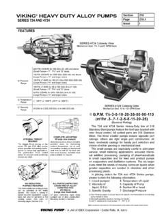
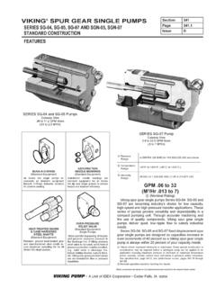
1 ENGINEERING SERVICE BULLETIN ESB-31 Page 1 of 6 Effective: 12-16-10 Supersedes: 5-27-85 To: MASTER CATALOG HOLDERS subject : VIKING pressure relief VALVES This Engineering Service Bulletin deals with the terminology and some typical questions asked with regards to the performance of VIKING pressure relief valves. In general, the terminology and answers given apply to the following types of valves shown below: TERMINOLOGY OF VIKING pressure relief VALVES 1. Cracking pressure : The cracking pressure (refer to Figure 4) is the pressure at which the valve begins to open and bypass liquid. The cracking pressure is not affected by pump size, pump capacity, or liquid viscosity.
2 The pump will deliver full capacity (except for slippage loss) at the cracking pressure . Most commercial relief valves use the cracking pressure as their valve setting. The relief valve size is selected by the amount of over pressure desired ( pressure between cracking and complete bypass). This over pressure is determined by the capacity and liquid viscosity. 2. Complete Bypass pressure : The complete bypass pressure (refer to Figure 4) is the pressure at which the entire capacity of the pump is bypassing through the relief valve. No liquid is going through the discharge line. At VIKING , this pressure is referred to as the valve setting. This pressure is stamped on a small boss on the valve body when shipped from VIKING .
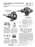
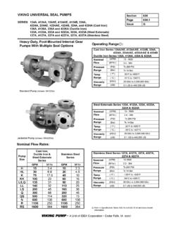
3 VIKING relief valves are normally set in 25 psi increments. Figure 4 Figure 2 Pump Mounted Return-To-Tank pressure relief Valve TO INLET LINE OR SUPPLY TANK ADJUSTABLE SETTING FROM PUMP DISCHARGE Figure 3 In-Line pressure relief Valve Mounted in Discharge Line TO INLET LINE OR SUPPLY TANK Figure 1 Pump Mounted Internal pressure relief Valve VIKING pressure relief VALVES ESB-31 PAGE 2 OF 6 VIKING PUMP, INC. A Unit of IDEX Corporation Cedar Falls, IA 50613 USA 3. Complete Bypass pressure Range: Several springs or spring combinations are used in VIKING s relief valves. With these springs and the use of the relief valve adjusting screw, various complete bypass pressures can be obtained.
4 Each spring in a particular relief valve will produce a pressure range which is determined by the adjusting screw. The Minimum Complete Bypass pressure is when the adjusting screw is backed out until loose, which allows the relief valve spring to be fully extended within the valve body. With the adjusting screw turned in completely, the Maximum Complete Bypass pressure is obtained. The Complete Bypass pressure Range is the pressure from the Minimum Complete Bypass pressure to the Maximum Complete Bypass pressure . The pressure Range PSI column on the Parts List ( CATALOG Section R620) represents the Complete Bypass pressure Range.
5 Because of the overlap of the springs, each spring may go below and above the range indicated in the Parts List. FREQUENTLY ASKED QUESTIONS Listed below are some typical questions asked about the performance of the VIKING pressure relief Valves: Q) What is the relationship between cracking pressure and complete bypass pressure ? A) The cracking pressure is always less than the complete bypass pressure as shown in Figure 4. The charts on page 5 and 6 show the actual relationship for valves mounted on pumps. The higher the capacity, the greater difference between cracking and complete bypass pressure .
6 Doubling the capacity will nearly double the difference between cracking and full bypass. Higher viscosity liquids will increase the difference because of higher resistance of the more viscous liquids. Higher pressure settings will also increase the difference because of higher spring rates required for the high pressure settings. Q) Why does the pressure range for a given spring increase as the pump size increases as shown in the Parts List? A) As the volume of the liquid through the relief valve increases, the poppet in the valve must rise higher to allow the liquid to bypass. This requires additional compression of the spring, which requires higher pressure .
7 Q) Can the VIKING Return-To-Tank pressure relief and In-Line pressure relief Valves (Figures 2 and 3) be used as a capacity regulating device? A) In cases where the system to which the pump is delivering liquid has a variable resistance to fluid flow, the Return-To-Tank pressure relief and In-Line pressure relief Valves can serve as a capacity regulating device. Examples of this would be multiple LPG bottle or tank filling systems. For instance when only one bottle on a manifold is being filled at a time, the valve will open and bypass the quantity of liquid that cannot be forced through the system. Refer to Figure 5.
8 Note: The pump mounted Internal pressure relief Valve (Figure 1) is not recommended for use as a capacity regulating device. Figure 5 Several points should be considered when the VIKING Return-To-Tank pressure relief and In-Line Pres-sure relief Valves are being considered for use as a capacity regulating device: 1. The pump will of necessity be handling considerably more liquid than is going through the system. This means the pump must be larger than required for the system, the motor will be larger than necessary, and it will cost more to operate. 2. When operating at pressures higher than the cracking pressure , a slight change in pres-sure results in a large change in capacity.
9 This makes it difficult to accurately predict the capacity at pressures above the cracking pressure . 3. VIKING does not recommend the use of VIKING Return-To-Tank pressure relief and In-Line pressure relief Valves in place of the more conventional regulating devices. VIKING pressure relief VALVES ESB-31 PAGE 3 OF 6 VIKING PUMP, INC. A Unit of IDEX Corporation Cedar Falls, IA 50613 USA Q) Should the motor horsepower for a unit be determined by the horsepower required at the complete bypass pressure or at the cracking pressure of the valve? A) The relief valve curves on pages 5 and 6 give the relationship between cracking pressure and the complete bypass pressure .
10 The motor size determination should be made based on the application. In many cases, the motor horsepower increments will cover both the cracking (operating) pressure and the complete bypass pressure . When this is not the case, then: 1. If the application calls for frequent full opening of the relief valve, the motor should be sized to cover or nearly cover the complete bypass setting. 2. If the relief valve is to serve strictly as an over pressure relief device with no additional use except under an unusual set of circumstances, then the motor size can be selected based on operating pressure .