Transcription of Tools, Installation, Operation, Maintenance
1 Tools, installation , Operation and Maintenance Safe, efficient operation of any product is inherently dependent upon its proper installation . In this section the preparation and assembly of low, medium and high pres- sure connections is explained. Also covered is the assembly procedure for medium and high pressure anti-vibration collet gland assemblies . Correct installation procedures are further promoted by providing dimensional information associated with a variety of Parker Autoclave Engineers tube connections as well as the torque required to properly seat numerous Parker Autoclave Engineers components. Several tools developed by Parker Autoclave Engineers are presented to help accomplish proper valve, fitting and tubing installation and Maintenance . Tools, installation , Operation and Maintenance When installing or maintaining any pressure component, common practice dictates the use of proper safety equipment at all times. All general terms and conditions of sale, including limitations of our liability, apply to all products and services sold.
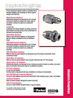
2 1. Tools, installation , Operation and Maintenance - installation Parker Autoclave Engineers Speedbite Connections Fast, Positive Sealing for Pressures up to Complete Connection 15,000 psi* (1034 bar) The illustration below shows the condition of sleeve and tubing after completion of sleeve seating. The sleeve has 1. Cut tubing to length and deburr. Allow extra length for cut into the tubing as it moved forward into the tapered seat, proper engagement (per table below). upsetting material ahead of it and establishing a shoulder on the tubing to provide positive mechanical support for the Outside Diameter Extra Allowance**. Tube Size for Engagement tubing end-load. A properly seated sleeve cannot be displaced inches (mm) inches (mm) back and forth along the tubing but may be rotated around the tubing. 1/16 ( ) ( ). 1/8 ( ) ( ). Reassembly 1/4 ( ) ( ). To reassemble a connection, insert tubing with sleeve and 3/8 ( ) ( ). gland into valve or fitting. Tighten gland finger-tight.
3 Tighten 1/2 ( ) ( ) gland with a wrench approximately 3/8 of a turn for a gas- tight seal. After frequent reassemblies, it may take less than 2. Lubricate male threads. (Lubrication not necessary if tube 3/8 turn to effect a gas-tight seal, and as little as 1/8 of a turn nut has Bonded Dry-Film Lubricant.) Slip gland and sleeve may be sufficient. onto tubing. Note: Be sure to remove gland and sleeve from components and slide them onto the tubing before inserting the tubing into SpeedBite the components. Make sure larger end of sleeve is toward "SW" and "W" Style gland. Push tubing into valve or fitting until it bottoms. If process tolerable, a slight amount of inert grease on the nose of the compression sleeve will improve sealability. 3. TIGHTEN GLAND UNTIL SLEEVE BEGINS TO GRIP. TUBING. 4. Note starting position of wrench. Tighten gland approxi- mately 1-1/4 turns for the SW and 1/8" W connection. For 1/4" Gland See Note **. and 1/2" W connections tighten glands approximately 1 turn, Larger end of sleeve toward gland for adapter approximately 1/8 turn.
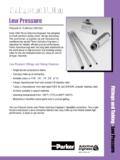
4 Fitting Bite into tubing Step 1 Step 2 exaggerated for clarity * No special torque wrenches or mandrels required. ** Distance tubing protrudes into connection from face of fitting. Fitting to Fittings Distance Step 3 Step 4 Fitting to Fitting Distance + (2 x Extra Allowance from Table #1). + (2 x 1/16 Finish Allowance). Cut Length Determine Tube Length Fully annealed tubing with proper outside diameter tolerances is recommended for these connection components. 2 All general terms and conditions of sale, including limitations of our liability, apply to all products and services sold. Tools, installation , Operation and Maintenance - Manual Coning & Threading Tools Manual Coning & Threading Tools Parker Autoclave Engineers manufactures a manual coning and For threading operations the threading die holder is designed threading tool for optimum performance with tubing sizes up to hold the appropriate die for any of the standard Parker to 9/16 ( mm) outside diameter.
5 These precision qual- Autoclave Engineers tubing sizes through 9/16 ( mm). ity manual tools permit on-site end preparation for Parker outside diameter. Interchangeable guide bushings properly Autoclave Engineers medium and high pressure tubing installa- guide the tool for accurate thread cutting. tions. One coning and one threading tool with optional sizes of collets, blades, dies and guide bushings eliminates the need of multiple tools for different size tubing. Interchangeable collets for each size tubing provides proper Coning Tool centering of tubing. The cutting feed arrangement permits the operator to control the length of the cut. Interchangeable tool steel cutting blades are used in pairs to assure more accurate and faster coning. They are designed to square-off and finish Cutter Support the tube as the cone is completed. There is a provision for ap- plying metal cutting lubricants to the cutting zone. Feed Nut For coning tool with optional sup- Coning Tool Threading Tool port arm (For holding in vise) and Housing chip/oil catch reservoir, add RS to suffix of model number.
6 Collet Nut Example: MCTM4-RS Note: Collet nut wrench (not shown) supplied with coning tool. Reservoir Support Arm Tube Size Coning Tools and Components Catalog Number Threading Tools and Components Catalog Number Tool Tool Outside Inside Coning Threading Die with with guide Diameter Diameter Blades Tool Collet & Die & Bushing in.(mm) in.(mm) Collet (set of 2) Only Order No. Size-type*. Blades Bushing Parker AE Medium Pressure 1/4 ( ) .109 ( ) MCTM4 90248 101F-1577 402A 402 P-0214 1/4-28 1010-0343. 3/8 ( ) .203 ( ) MCTM6 90250 101F-1601 402C 402 P-0215 3/8-24 1010-0344. =9/16 ( ) .312 ( ) MCTM920 90251 1010-5218 402E 402 P-0216 9/16-18 1010-0345. 9/16 ( ) .359 ( ) MCTM910 90251 101A-1897 402E 402 P-0216 9/16-18 1010-0345. 1/4 ( ) .083 ( ) MCTH4 90248 101F-3939 402A 402 P-0214 1/4-28 1010-0343. Parker AE High Pressure 5/16 ( ) .062 ( ) MCTH5 90249 101F-3939 402B 402 P-0205 5/16-24 1030-0343. 3/8 ( ) .125 ( ) MCTH6 90250 101F-1578 402C 402 P-0215 3/8-24 1010-0344.
7 9/16 ( ) .188 ( ) MCTH960 90251 1010-0883 402E 402 P-0216 9/16-18 1010-0345. 9/16 ( ) .250 ( ) MCTH940 90251 101C-7214 402E 402 P-0216 9/16-18 1010-0345. Options: Cutting Oil: P-8784 MCT-SA: Support Arm Assembly 90286: Instructions MCT-RES: Reservoir Assembly * All threads for Parker AE medium pressure and high pressure tubing are LH national fine (class 2). = 9/16 ( ) x .312 ( ) ID 40,000 psi (2758 bar), use MCTM920. Note: Manual coning and threading tools for 3/4" ( mm) and 1" ( mm) outside diameter medium pressure tubing are not available. Model AEGCTM-2 Power Coning-and- Threading Machine is recommended for this tubing. A minimum of 3" (76 mm) straight length is required to perform coning and threading operation with manual coning tool. All general terms and conditions of sale, including limitations of our liability, apply to all products and services sold. 3. Tools, installation , Operation and Maintenance - Coning, Coning & Threading Kits Coning and Coning and Threading Tool Kits Parker Autoclave Engineers offers coning kits as well as con- ing and threading tool kits.
8 Each kit consists of the required tools and other items necessary for your coning or coning and threading needs. All kit items are placed in a hand-carry tool case with top tray. The coning tools supplied in the tool kits come complete with the support arm and chip/oil reservoir. Coning and Threading Kit: Included with all kits: Coning tool assembly, three collets, col- let nut wrench, three sets of coning blades, tool box with tray, de-burring tool, one quart of cutting oil, 3/32 Allen wrench, four spare set screws, threading tool, three guide bushings, three threading dies, and laminated instruction sheet. Medium pressure kit KMCT-MT Coning tool with support arm and reservoir 1/4, 3/8 and 9/16 collets 1/4, 3/8 and 9/16 blades (9/16 blades for 20,000 psi tubing only). Threading tool 1/4, 3/8 and 9/16 guide bushing 1/4, 3/8 and 9/16 dies High pressure kit KMCT-HT Coning tool with support arm and reservoir 1/4, 3/8 and 9/16 collets 1/4, 3/8 and 9/16 blades (5/16 collets not included).
9 (9/16 blades for 60,000 psi tubing only). Threading tool 1/4, 3/8 and 9/16 guide bushing 1/4, 3/8 and 9/16 dies Note: Additional blades available for other sizes of tubing. See manual coning and threading tool on page 3 for sizes and part numbers. 4 All general terms and conditions of sale, including limitations of our liability, apply to all products and services sold. Tools, installation , Operation and Maintenance - Coning & Threading installation Coning and Threading installation Manual Kit: 3. Fig. 2 Place the coning tool housing 1. Fig. 1 Cut tubing to length and Fig. 2. Fig. 1 (or optional support arm), without the square off the end as close to the feed nut/cutter support assembly, in a required length as possible. Allow extra vise. The vise should be equipped with length for proper engagement into the connection as listed in Table 1. A soft jaws, and the housing should be small amount of extra length should be placed in the vise to allow lubricant to allowed to finish the end of the tube, flow to the cutters and cone.
10 But excessive amounts require addi- 4. Fig. 2 Slide the tubing through the tional cutting time and premature blade collet until the end of the tube appears wear. Note: When cutting tubing with abrasive cut off wheel, tubing should in the coning tool housing window. Line not be over heated effecting material the end of the tube with the edge of the properties. window and tighten the collet nut firmly in place using the collet nut wrench (see Table 2). 2. Install the collet and collet nut into the bottom of the coning tool housing. Remove the cutter support feed nut from the coning tool housing and install 5. Fig. 3 Install the feed nut/cutter support assembly into the coning tool the cutters. This can be done by backing out the four set screws in the cutter housing. Rotate the feed nut clockwise until the top of the cutters just con- support. Note: When installing new blades, be sure the blades are flat against tact the top of the tube. Do not rotate the holder.