Transcription of TORQUE CONTROL FOR VARIABLE SPEED WIND TURBINES
1 ECN-RX--04-125 TORQUE CONTROL FOR VARIABLE SPEED wind TURBINES P. Schaak van Engelen This paper has been presented at the European wind Energy Conference, London, 22-25 November, 2004 NOVEMBER 2004 TORQUE CONTROL for VARIABLE SPEED wind TURBINES Pieter Schaak, Tim G. van Engelen Energy research Centre of the Netherlands, ECN wind Energy Box 1, 1755 ZG Petten, The Netherlands telephone: +31 224 56 4278, fax: +31 224 56 8214 e-mail: web: Abstract: An advanced generator CONTROL algorithm has been developed and implemented in ECN s CONTROL design tool for wind TURBINES .
2 For wind speeds above nominal the algorithm limits power and rotor SPEED to the common bounds of constant power CONTROL in VARIABLE SPEED TURBINES , while the electromagnetic TORQUE varies half as much as found in literature. Simultaneously production dips at above nominal wind speeds are avoided. The algorithm has been examined by the aero-elastic wind turbine code Phatas. Application on a commercial wind turbine is in preparation. Keywords: CONTROL , converter, generator, power, TORQUE , VARIABLE SPEED , wind turbine .
3 1. Introduction For wind speeds above the nominal wind SPEED , conventional generator CONTROL algorithms of VARIABLE SPEED TURBINES result in production dips. Some currently applied TURBINES still suffer from this undesired phenomenon, although literature offers a solution since at least one decade. This paper explains how the algorithm that has been implemented in ECN s CONTROL design tool prevents for the production dips and why our algorithm excels on TORQUE behaviour.
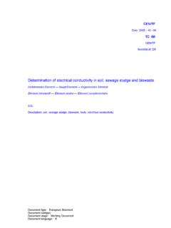
4 Simulations at wind speeds above the nominal wind SPEED show that our algorithm reduces TORQUE variations by 50%, compared to the algorithms found in literature. 2. Literature In VARIABLE SPEED wind TURBINES a relatively fast servo controller sets the electromagnetic generator TORQUE on the basis of rotor SPEED measurements. A conventional SPEED - TORQUE relation is shown in figure 1 [5]. This relation is based on the partly dashed curves for optimum Lambda and full load CONTROL .
5 The optimum Lambda curve aims to maximise the aerodynamic efficiency of the turbine by aiming the optimum Lambda, the optimum tip SPEED ratio. The full load curve describes the SPEED - TORQUE combinations that result in nominal generator power. As a consequence of operational restrictions those 2 curves usually cannot be applied up to the operating point that they have in common. Therefore the transition curve has been introduced. Applying a minimum rotor SPEED as well completes the figure.
6 During full load operation a blade pitch controller strives to maintain a desired rotor SPEED that lies on or a little above the nominal rotor SPEED . When the rotor SPEED deviates from the desired rotor SPEED , due to raising or falling winds, the blades are pitched to overcome this deviation. For falling wind , this is maintained until the power that is extracted from the wind no longer can be increased by pitching the blades. Then the rotor will decelerate and the generator TORQUE will be controlled on the basis of the transition curve of figure 1.
7 Of course blade pitching does not follow wind SPEED changes instantaneously. So during full load operation the rotor SPEED fluctuates around the desired rotor SPEED and, despite pitching the blades, the transition curve of figure 1 also then becomes applicable sometimes. The rotor SPEED , the TORQUE and thus the power decrease below nominal and a production dip during full load operation has arisen. This still occurs on some nowadays TURBINES [7]. As long as blade pitching can be used to increase the rotor SPEED , a too low rotor SPEED will be cancelled out by blade pitching, almost regardless the SPEED - TORQUE relation that is applied.
8 So the production dips will be prevented by applying the dashed part of the nominal power curve instead of the transition curve, in the case that blade pitching lags behind a falling wind [1,2]. loadPnomTnom nomoptimum Lambdatransitiontorqueconventional characteristic rotor SPEED file e:\schaak\ctrltool\report\ 24-Apr-2003 by e:\schaak\ctrltool\m\ 1: Conventional SPEED - TORQUE relation, normalised on nominal operation.
9 The inevitable leaving of full load operation is announced when blade pitching no longer can increase the rotor SPEED . Only then the full load curve should be left. In figure 1 the operational point will be at the left side of the conventional transition curve then and TORQUE CONTROL must be adapted to the conventional SPEED - TORQUE relation gradually. Remark that the TORQUE CONTROL that prevents for production dips also allows to move the conventional transition curve a little to the right, because it can connect to the full load curve above the at full load desired rotor SPEED now.
10 Further the transition could be realised by constant SPEED servo CONTROL as well and sometimes full load operation is realised by a horizontal constant TORQUE curve [1,2]. 3. Novel views on full load TORQUE CONTROL During full load operation pitching the blades controls the rotor SPEED . The TORQUE and power behaviour follows via the SPEED - TORQUE relation. Applying a different but also proper SPEED - TORQUE relation barely influences the rotor SPEED . That means that the full load curve always should lie somewhere in the shaded area of figure 2, because outside this area either the applicable power or the applicable TORQUE range is enlarged without obtaining a profit in change.