Transcription of Trabon - CENTRAL-LUBE
1 Modu-Flo Product Specs and Ordering LUBRIQUIP, INC., A Unit of IDEX Corporation July 1985. All Rights 12000 Trabon Modu-Flo Pumps Reservoirs Lube PackagesAccessories Modu-FIo concept provides a proven, cost-effective wayto assemble customized oil or grease lubrication systemsthat meet specific requirements by using standardmodular components. Modu-Flo increases opportunities to standardize lubesystem components and reduces lube maintenance andservice costs. Modu-Flo saves you system design dollars and lead time. Modu-Flo components are dependable and backed bythe industry s most comprehensive international distribu-tor network with application expertise, stocked partsand factory-trained service nearby, wherever you CORPORATIONR evised April 2002 Trabon Modu-Flo Page 2 Bulletin 12000 RModu-FIo = true modularityWide choice of standard modular components helps you meet applicationrequirements more exactly without the added cost of a custom :Helps provide as much or as littleautomation and sophistication as yoursystem requires.
2 For details, see page LUBE PACKAGES:Use one part number to get the exact reservoir /manifold /pump package plus the modular matchedaccessories you need. See pages 8, 9,10,11 andordering menu on back MOUNTING MANIFOLD:One model permits remote wall mounting of anyModu-Flo pump. See page PUMPST hree basic pneumatic pumps with single ordouble action for oil or grease; three double-acting hydraulic-actuated pumps for oil orgrease. All with adjustable stroke. For details,see pages 3 & ACCESSORIES:For data on 3-way air solenoid (for pneumaticpumps), pressure gauge, fill check, high pressureblowout and pressure switch, see page MANIFOLD:One model fits all, mounts choice ofaccessories. See page RESERVOIRS:Tank type and cylindrical, metal andplastic, for pump or remote details, see pages 6 & ACCESSORIES:High pressure indicators and blowouts plus low-level indicators, switches, and switch assem-blies.
3 For details, see page 3 Bulletin 12000 Trabon Modu-Flo RModu-Flo PUMPSP neumatic AL PumpHydraulic HLJ PumpThere are six Modu-FIo pneumatic and hydraulic actuated pumpmodels for series progressive oil or grease systems. Threepneumatic models carry the AL prefix. They are actuated by airpressure from 40 to 150 psi ( to bar), and have a lube-to-airpressure ratio of 30:1. They can be set up to be single-or double-acting, depending on the system hydraulic-actuated models carry an HLJ prefix. They are double-acting, operate on hydraulic pressure from 200 to 2,000 psi ( bar), and have a lube-to-hydraulic pressure ratio of :1. TheHLJ-5X has a lube to hydraulic ratio of :1. All six models fit eitherthe Modu-Flo pump-to-reservoir mounting manifold or the remotewall mounting / BENEFITS Adjustable displacement at the turn of a screw provides aninfinite choice of outputs within output range of each pumpmodel.
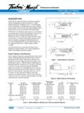
4 All Modu-Flo pumps can be used with either oil or grease. All Modu-Flo pumps can be used with any of the 23 used in single-acting mode, air under pressure is suppliedthrough the inlet port (SA) to chamber (C). This moves the air andlube pistons to the right. This closes the lube inlet port and forcesthe lubricant already in chamber (B) past the check valve and intothe system. Air in chamber (A) must vent out port (DA). A plasticpipe plug with a vent hole is installed in port (DA). After a preset timeinterval the solenoid valve shuts off the air supply and ventschamber (C) through port (SA). The spring returns the air and lubepistons, opening chamber (B) to the lube reservoir. This completes asingle pump cycle and chamber (B) is primed, ready for the used in double-acting mode, an additional air or hydraulicsupply line is connected to port (DA). When the pistons have beenmoved to the right, air or hydraulic supply to port (SA) is shut-off andvented.
5 Then, air or hydraulic fluid under pressure is supplied to port(DA), which returns the pistons to their original position. This morepowerful return action allows an increased cycle rate of the (. )*.XAMSELCYCREPETUNIM-XORPPAETAMI)gk(.bl ,.tWGNITAREPOEMULOVLLUFREPELCYC/EKORTSMC (. ) ) ( ) ( ) ( ) ( ) ( ) ( ) ( ) ( ) ( ) ( ) ( ) ( ) ( ) ( ) ( ) ( ( ) (ETON rebmuntrapemasehtevahnoitarepognitca-elb udro-elgnisrofspmup)ria(LA:).4egapeeS( ) ( ) ( ) ( ) ( ) ( ) ( ) ( ) ( ) (ETON.) ( (isp000, )rab702()xam(isp0003dna,) )ffosdnoces3,nosdnoces3(esaerghtiwmpc01d eecxetonoD*ADJUSTING DISPLACEMENTA fter the pump is removed from service, remove the calibrated capthat protects the adjustment screw. Loosen the hex nut and twowashers. Then use a screwdriver to turn the adjustment screwoutward to increase displacement or inward to reduce the calibrated cap parallel to the screw to gauge the amount ofchange (Cap is graduated at minimum, 1/4, 1/2, 3/4 and maximumoutput).)
6 When the proper setting has been made reposition thewashers and tighten the hex nut, replace the cap, and return thepump to : System should NOT be operating while adjustments aremade; however, it is not necessary to remove the pump or discon-nect any : Refer to bulletin 12011 for electricmotor operated Modu-Flo Modu-Flo Page 4 Bulletin 12000 RHYDRAULIC PUMPS (HLJ)ORDERING INFORMATIONUse the following part numbers only if you are NOT orderinga Modu-Flo Lube : Single- and double-acting pneumatic pumps (AL)have the same part DIMENSIONS / Inches (mm)PNEUMATIC PUMPS (AL)PMUPLEDOM)mm(sehcnI/SNOISNEMIDABCEF ) ( ) ( ) ( )45( )37( ) ( ) ( ) ( ) ( ) ( )37( ) ( ) ( ) ( ) ( ) ( ) ( )18( )801( ) ( ) (Pump Repair KitsPart NumberFor AL-5, single- or AL-25, single- or AL-50, single- or ModelPart NumberAL-5, pneumatic 30:1 ratio(. in3/stroke) (. cc).
7 521-000-001AL-25, pneumatic 30:1 ratio(. in3/stroke) (. cc)..521-000-021AL-50, pneumatic 30:1 ratio(. in3/stroke) (. cc)..521-000-041 HLJ-5, hydraulic :1 ratio(. in3/stroke) (. cc).. 521-000-011 HLJ-25, hydraulic :1 ratio(. in3/stroke) (. cc)..521-000-031 HLJ-5X, hydraulic :1 ratio(. in3/stroke) (. cc)..521-005-900 Page 5 Bulletin 12000 Trabon Modu-Flo RMANIFOLDST here are just two types of modular design manifolds for direct-to-reservoir or remote mounting of Modu-Flo Pumps. Bothmount any pneumatic or hydraulic Modu-Flo pump and both typescontain all of the pneumatic (or hydraulic) connections and lubricantORDERING INFORMATIONModu-Flo Pump-to-wall or remote manifold (521-001-170)(Shown assembled)**MANIFOLD/ACCESSORYCOMBINATIO NSACCESSORIES FOR MANIFOLDPART NUMBERPump/Reservoir Manifold only (NPT) ..521-001-540 Pump/Reservoir Manifold (NPT).
8 521-001-180 Includes outlet check valve, system fill check valve,blowout assembly, and 0-3000 psi pressure Pump Manifold (NPT) ..521-001-170 Includes outlet check valve, system fill check valve,and blowout Manifold (NPT) with outlet check valve, system fillcheck valve, tubed blowout assembly, and 0-3000 psi Pump Manifold (NPT) with outlet check valve, system fillcheck valve, and tubed blowout 521-001-780 Pump/Reservoir manifold (SAE) includes outlet check valve, systemfill check valve, blowout assembly and : For ratings on spare and/or replacement blowout discs, seepage other port thread options, contact necessary. This allows the pump to be removed withoutdisturbing existing lines or emptying the reservoir. Also, Modu-Flomanifolds may be used as is, or can be fitted with a choice ofmatched accessories. (See illustrations and listings that follow.)
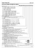
9 PART NUMBERYou can order the manifold and accessories you want separately or with one part number, as shown below. If you intend to order the pump,reservoir, manifold and accessories at one time, check the section in this brochure beginning on page 8 titled Modu-Flo Lube Packages. * Manifolds are intended for gravity feed (oil) or spring loadedfollower feed (grease) only.* * Manifolds/Accessory combinations are shipped withaccessories not assembled to / Inches (mm)Outlet Check Valve (NPT) ..509-360-030 System Fill Check Valve (NPT)..509-365-030 Standard Blowout Assembly, 1,450 psi( bar) (NPT)..509-206-100 Tubed Blowout Assembly, 1,450 psi( bar) (NPT)..509-220-101 Standard Pressure Gauge, 3,000 psi( bar) (NPT)..543-363-000 Liquid filled Pressure Gauge, 3,000 psi( bar) (NPT).. 543-711-380 Outlet Check Valve (SAE)..463-001-587 System Fill Check Valve (SAE).
10 463-001-600 Standard Blowout Assembly, 1,450 psi( bar) (SAE)..509-206-110 Standard Pressure Gauge, 3,000 psi( bar) (SAE)..493-020-242 Gauge Adapter (SAE) 7/16-20 to 9 412-700-545 Pump-to-reservoirmanifold (521-001-180)(Shown assembled) Trabon Modu-Flo Page 6 Bulletin 12000R23 Modu-Flo Reservoirs are available for use with any Modu-Flo Pump or as a separate are available in the following configurations and capacities: Cylindrical types in plastic and metal are available withgrease capacities of 3, 5, 6,12, 20, and 40 lbs. ( , , , , and kg). Cylindrical types in plastic are available with oil capacities of5, 6, 12 and 20 pints ( , , and liters). Rectangular types in metal are available with oil capacities of12, 24 and 40 pints ( , and liters). Metal reservoirs are equipped with level Modu-Flo RESERVOIR DIMENSIONS / Inches (mm)CYLINDRICAL PLASTIC OIL RESERVOIRSRECTANGULAR METAL OIL RESERVOIRS(For Larger Capacity Reservoirs, Contact Factory)CYLINDRICAL METAL & PLASTIC GREASE RESERVOIRSM etal grease reservoir illustrated at right*See Note 3, Page 12.