Transcription of Trabon Divider Valves - Graco
1 InstructionsFor series progressive, oil and grease lubrication. For Professional Use PressureTable 1: Maximum Pressure Lube PointsSTable 2: MGO Series-Flo Divider Maximum Operating PressuresImportant Safety InstructionsRead all warnings and instructions in this manual. Keep these TypeMaximum Operating Pressure kPSI (MPa, bar)Maximum ( , 207) ( , 138)8 ( , 241)11 ( , 517) ( , 207) ( , 207)10 MGOSee Table 211 Maximum Operating Pressure kPSI (MPa, bar)Number of ( , 414)3 to ( , 379) ( , 276) ( , 310) ( , 276)11312497 TENT rabon Divider Valves Warnings 2312497 TWarningsThe following Warnings are for the setup, use, grounding, maintenance and repair of this equipment.
2 The exclama-tion point symbol alerts you to a general warning and hazard symbols refer to procedure-specific risks. Refer back to these Warnings. Additional, product-specific warnings may be found throughout the body of this manual where MISUSE HAZARD Misuse can cause death or serious injury. Do not operate the unit when fatigued or under the influence of drugs or alcohol. Do not exceed the maximum working pressure or temperature rating of the lowest rated system component. See Technical Data in all equipment manuals. Use fluids and solvents that are compatible with equipment wetted parts. See Technical Data in all equipment manuals. Read fluid and solvent manufacturer s warnings.
3 For complete information about your material, request MSDS forms from distributor or retailer. Check equipment daily. Repair or replace worn or damaged parts immediately with genuine manufacturer s replacement parts only. Do not alter or modify equipment. Use equipment only for its intended purpose. Call your distributor for information. Keep children and animals away from work area. Comply with all applicable safety INJECTION HAZARD High-pressure fluid from dispense valve, hose leaks, or ruptured components will pierce skin. This may look like just a cut, but it is a serious injury that can result in amputation. Get immediate surgical treatment. Do not point dispense valve at anyone or at any part of the body.
4 Do not put your hand over the end of the dispense nozzle. Do not stop or deflect leaks with your hand, body, glove, or rag. Follow Pressure Relief Procedure in this manual, when you stop spraying and before cleaning, checking, or servicing equipment. CALIFORNIA PROPOSITION 65 This product contains a chemical known to the State of California to cause cancer, birth defects or other reproductive harm. Wash hands after Relief ProcedureFollow the Pressure Relief Procedure whenever you see this Verify pump feeding valve is stopped and discon-nected from, or locked out of it s Using a wrench, slowly loosen inlet Then, using a wrench, slowly loosen each port Divider valve is shipped ready to install in your sys-tem.
5 It has been factory-tested and should not require any additional MJ and MX series Valves only: Gaskets (a) must be installed between every valve section (b) of the block assembly to prevent install the Divider valve in your system:1. Determine an appropriate, remote mounting Install a rupture to atmosphere fitting with a blow-out disk that is rated for 7,500 psi (52 MPa, 517 bar) or less between the force feed lubricator pump and master Divider valve Install an analog pressure gauge at the inlet to the Divider Install a slow or no cycle shutdown in one of the pis-ton enclosure plugs. Program it to shut down after no more than 180 seconds without a complete Torque. See Table 4 on page long as lubricant is supplied under pressure to the inlet section of the Divider assembly, Valves sections will continue to operate in a progressive manner.
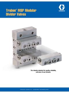
6 Divider assemblies always follow a constant discharge pattern. Whenever lubricant flow ceases, the valving pistons will stop. When flow resumes, it will start again at the same point in the discharge equipment stays pressurized until pressure is manually relieved. To help prevent serious injury from pressurized fluid, such as skin injection, splashing fluid and moving parts, follow the Pressure Relief Procedure when you stop spraying and before cleaning, checking, or servicing the 1abbNOTICEDo not install a Divider valve into a system rated for more than the valve s maximum operating pressure. This type of installation could result in o-ring damage and cause the Divider valve to 4312497 TComponent IdentificationKey:AValve SectionBInlet SectionCIndicator / Port PlugDCrossport PlateEEnd PlugFSubplates with Outlet PortsGEnd SectionHTie Rod NutTable 3: Typical Divider Valve CombinationsDivider ValvesA Series-Flo type Divider valve is a manifold proportion-ing device consisting of an inlet and end section plus a minimum of three valve sections.
7 The Divider valve is manifolded together with tie rods and nuts. A master Divider valve is the first Divider valve downstream from the lube pump. A secondary Divider valve is any Divider valve receiving lubricant from the master Divider Sections (MSP, MHH and MXP modular-type, Divider Valves , only)Valve sections (three or more required per manifold) contain a piston specially fitted to that section, built in outlet check Valves and various passageways that, working with the piston, meters and Valves the flow of lubricant (FIG. 3). Valve sections may be manufactured to require one or two lube outlets. Stamping located on the face of each section indicates: the style of Divider valve section, , MSP, MX, etc.
8 , the discharge per piston stroke expressed in thousandths of cubic inches (35 = .035 in3 ) and, the number of lube outlets required (S = single, one outlet only; T = twin, two lube outlets required).FIG. 2 MASTERSECONDARYTYPE OF APPLICATIONMJMD Machine tools, Printing, Wire Forging & Packaging MachineryMSPMJ, MSPM achine tools, Textile, Glass & Can Machinery, Mobile EquipmentMX, MXPMX, MXP, MSPC ranes, Presses, Steel Mills, , Shears, Conveyors, 3TI11102 PistonEnclosure/EndEnclosure Plug GasketPistonIndicatorIndicator Port PlugPortO-RingsCheckValvePlug Setup312497T5 Prefilling Lubricant Distributor LinesFollow the following procedure exactly as written, in the order Secondary-to-Lube Point LinesRefer to FIG.
9 4. when performing this Remove port plugs or performance indicators from all of the indicator ports on front of secondary Divider Connect a hand pump filled with clean, filtered lubri-cant to the indicator port closest to the first line to be filled that corresponds to the output port that is feed-ing the line to be In order to verify when lubricant is flowing and has reached the end of the lube line, loosen the connec-tor at the lube point of the line that is to be Stroke the hand pump until air-free lubricant is observed flowing from the end of the lube Tighten the lube line connector at the lube point, but do not replace the port plugs or performance indica-tors into the ports on the front of the working Repeat steps 1-5 for each of the other lube lines connected to the other outlet ports in the secondary Divider valve assembly and for any other secondary Divider assemblies in the : Do not replace any of the performance indicators or port plugs removed in Step 1 until the line-filling pro-cedure described in Section 2 (Filling Master -to-Sec-ondary Lube Lines) has been Master-to-Secondary Lube LinesRefer to FIG.
10 5. when performing this Remove the port plugs or performance indicators from all the indicator ports on the front of the master Divider Connect a hand pump filled with clean, filtered lubri-cant to the indicator port closest to the lube output port that is feeding the line to the secondary Divider Stroke the hand pump to fill the line between the master Divider valve and secondary Divider The initial startup and operation is the most critical operating period for a newly installed machine in terms of potential for being damaged by unre-moved/unfiltered lubricant contaminants and lack of adequate lubrication. Proper prefilling of lubrication system ensures that lubricant is immediately avail-able to every lube point during machine startup, protecting them from damage.