Transcription of Transfer Gear Pumps - Process Pump Sales
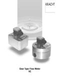
1 Transfer gear PumpsConstruction of the gear Pump KFKRACHTGmbH Gewerbestr. 20 D-58791 Werdohl Tel. 02392/935-0 Fax 02392/935209 Internet: e-mail: FeaturesKF gear Pumps are used for pumping a wide variety of gear Pumps are distinguished especially by their wide range of variants which are assembled as required on the modular principle and also permit subsequent Pumps are also suitable for media with low standard housing sections are of grey cast iron. The gear units are manufactured from high-strength case-hardening steel, hardened and mounted in specialmulti-compound plain bearing standard drive shaft is sealed by rotary shaft pump sizes incorporate helical tooth system.
2 This feature, combined with special gear geometry, results in extremely low noise levels and reduced pressure : Sealing of the drive shaftRotary shaft lip-type sealDouble rotary shaft lip-type seal (Quench)Mechanical seal Outboard bearing to take up input drive-side radial load Pressure relief valve as safety valve for pump and system Uniform discharge flow direction with changing directionof rotation by means of flange-mounting valve combination(universal device).Special ConstructionsTo meet your individual requirements on request specialconstructions are available: for instance mounting flangemodels, various types of plane bearings, Sales engineers will be glad to help you to equipmentmost appropriate for your specific Bearing BushEnd CoverHousingDriven Shaft PinionShaft End SealDrive Shaft EndOutboard BearingFlange Mounting CoverDriving GearTechnical DataKRACHTGmbH Gewerbestr.
3 20 D-58791 Werdohl Tel. 02392/935-0 Fax 02392/935209 Internet: e-mail: Dispersion of Discharge Flow Q as specified in the above Table may be:Q +2,5% up to 5%.At Viscosities of <30 mm2/s Reduction of the Discharge Flow Q. At Viscosities of >300 mm2/s, the Speed must be reduced. The Drive Motor Output must be selected 20% higher than the Data for P as specified in the above Table. For Viscosities of >100 mm2/s the Power Input must be increased. Characteristic Data at speedn = 1450 1 Pressure pbin Pressure pbin Flow Q in l/minPower Input Required P in kWSizeNominalGeometricalOperatingMaximum SpeedPerm.
4 ForcesMomentdisplacementdisplace-pressur epressurerange(n =1450 1/min)ofmentinertia*VgpbpmaxnminnmaxFrad ialFaxialJcm3barbar1/min1/minNNkgm23 *(without coupling) x10-4 RemarkOperating Pressure pb=Permissible Continuous PressureMaximum Pressure pmax=nur only applicable to the operation with Mineral Oils at Speed n > 700 1/min and Viscosities = 30 mm2/s up to 1000 mm2 Forces only applicable to the Types fitted with Outboard the middle of the Shaft KeyKRACHTGmbH Gewerbestr. 20 D-58791 Werdohl Tel. 02392/935-0 Fax 02392/935209 Internet: e-mail: NameEXAMPLEGear PumpsPressure Relief ValveNominalDisplacementKF 3100, 112KF 4125, 150, 180KF 5 200, 250, 315KF 6400, 500, 630 Direction of Rotation1 Clockwise2 Anticlockwise3 Clockwise and AnticlockwiseConstruction of Housingand Mounting SurfacesB Housing with Flanged PipeConnectionsKF3.
5 KF6 Shaft End (Drive)N Straight Shaft End with Outboard BearingP Straight Shaft End without Outboard BearingSeals (asbestos free)1 NBR-RotaryShaftLip-TypeSeals 90 C2 FPM-RotaryShaftLip-TypeSeals 150 C29 Mechanical Seals SAVGG 150 C30 Mechanical Seals SATGG 200 C32 PTFE-Rotary Shaft Lip-Type Seals 200 CHousing Materials and Seals (Cast Iron)Awith NBR-O-Ring 90 CDwith FPM-O-Ring 150 CCwithCu-Sealing-Ring 200 CEnd CoversAfor Dir. of Rotation1or 2 Bfor Dir. of Rotation30without End Cover( in the case of valve fitting)Pressure barSpecial Design , 4, 5, 6 Size^=KF3, 4, 5, 6KF3/112 DKF3D 047DP2/44P00F10 BSelectionFlange Mounting CoverFKF 3G KF 4H KF 5 / KF 6 Types of GearP Helical Gears KF 3.
6 KF 6 Selection Mounting EquipmentXMounting KF3 .. KF60without MountingDesignSerial-Nomber0(specified by Kracht)7 (specified by Kracht)Housing Material and Plain BearingsDCast Iron with Multicomponent Plain Bearing Bushes2. Shaft End (Throug Driver)0without Second Shaft End+KRACHTGmbH Gewerbestr. 20 D-58791 Werdohl Tel. 02392/935-0 Fax 02392/935209 Internet: e-mail: FluidsWaste oilsSoluble oilsDiesel oilsPrinting inksEmulsionsDyesFatsAntifreezeGear oilsAccessoriesFlanged Pipe Connections4-Bolt-Type Mounting AnglesPressure Relief Valves(attachable subsequently)Foot Mounting Flanges for the Adaptor Flanges belowBase PlatesCouplingsAdaptor Flanges(Pump Carrier)Other TypesZM.
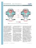
7 ZNPump with Electric Motor directly connected to each other by an Adaptor :The above specified Minimum and Maximum Characteristics are NOT applicable for some specific operating conditions: Maximum Operating Pressure is NOT permissible in conjunctionwith low speeds and low contact us whenever such critical ranges are Viscosity mm2/s <300300500100020003000600010000200003000 0 150012501000750600500400300200100max. Speed nmax1/minResinsHardening oilsFuel oils, L, EL, HHydraulic fluidsIsocyanateAdhesivesPlasticsEngine oilseNitrocellulose lacquersParaffinsPolyolsLubricating oilsCutting oilsHeavy oilsHeat Transfer mediaProcessing oilsWaxesRolling oilsDrawing compoundsOperating NotesPump running ccwPressure sidePump running cwSuction sideSuction sidePressure side when looking at the pump shaft end,the direction of pumping is from leftto right if the shaft rotates clockwise.
8 When looking at the pump shaft end, the direction of pumping is from right toleft if the shaft rotates of Rotation:The following should be noted for direction of rotation:With Pressure Relief ValveDrive shaft endWith our decades of experience, we are at your side, world-wide, for the professionalmastery of specific applications and complete solutions in hydraulics and Notes: The fluids should ensure a certain minimumlubricating properties, should not containsolids and should be chemically compatible. Avoid dry operation. The Pumps may only be operated in the specified direction of rotation, as otherwisethe shaft seal will be destroyed.
9 In order to prevent excessive overpressure, a safety valve should be provided in thesystem or on the pump. The pressure relief valve attached to thepump may only be used as safety valve forshort-term operation. To drain off a partial discharge flow over a prolonged period, a separate pressurerelief valve with return line must be insertedin the Kenngr enMountingFlange- and Angle Foot-TypePipe ConnectionFlanged Pipe Connections, 4-Bolt-Type(Straight Flange Couplings, Welding Connectors,in addition Intermediate Flange-Heatable).Threaded PortsDirection of RotationClockwise orAnticlockwiseClockwise andAnticlockwiseWeightRefer to Dimensional SheetsFitting PositionOptional (for exeptions refer to Universal Arrangement)Permissible Ambient u min= 20 CTemperature Range u max= + 60 COperating CharacteristicsOperating PressuresSuction Sidepe min= bar (Vacuum),(Inlet Port)for short time duty when starting: downto bars are permissible.
10 Observe thelimitation of pe minfor Pumps with UniversalArrangementi pe max= bar for PTFE-RotaryShaft Lip-Type Seals= bar for NBR- and FPM Rotary ShaftLip-Type Seals=10 bars for Mechanical 25 bars(Outlet Port)Fluid m min= 10 CTemperature m max=90 C for NBR-Rotary Shaft Lip-Type SealsRange=150 C for FPM Rotary Shaft Lip-Type Sealsand Mechanical Seals SAVGG=200 C for PTFE Rotary Shaft Lip-Type Seals=200 C for Mechanical Seals SATGG or refer to Page 4+5 Viscosity min=12 mm2/sRange max=15000 mm2/sViscosities other than within this range on requestDischarge FlowRefer to Table Page 3 Power InputRefer to Table Page 3 Speedsnmin=200 1/minnmax=2000 1/mnThe permissible max.


![BorgWarner eGearDrive(for customer) [兼容模式]](/cache/preview/a/d/d/9/8/4/2/5/thumb-add9842573e443c2740dc638242b6cd8.jpg)


